Eureka AIR delivers breakthrough ideas for toughest innovation challenges, trusted by R&D personnel around the world.

Sand mold casting device for sand core production

A sand mold and sand core technology is applied in the field of sand mold casting devices for sand core production, which can solve the problems of high failure rate, inability to ensure that the casting material is completely filled with membrane shells, etc., and achieve the effect of speeding up the feeding

Inactive Publication Date: 2019-12-17
溧阳市新明机械配件制造有限公司
View PDF8 Cites 3 Cited by
  • Summary
  • Abstract
  • Description
  • Claims
  • Application Information

AI Technical Summary

Problems solved by technology

[0002] Sand core is the material used to make the core in foundry production, which is composed of foundry sand, sand binder, etc., while sand mold casting needs to put the finished part model in the sand, and then fill the sand around the model to form a mold , the casting mold is kept for an appropriate time until the metal is solidified. After the part is taken out, the casting mold is destroyed, so a new casting mold must be made for each casting. Conventional sand casting, after the molten pouring material enters the mold, it completely relies on gravity to freely disperse to the film Therefore, it is impossible to ensure that the pouring material is completely filled with the membrane shell. At the same time, there are a large number of sand holes in the casting, and the failure rate is high, which needs to be improved urgently.

Method used


Image

  • Sand mold casting device for sand core production
  • Sand mold casting device for sand core production
  • Sand mold casting device for sand core production

Examples


Embodiment Construction

[0025] The following will clearly and completely describe the technical solutions in the embodiments of the present invention with reference to the accompanying drawings in the embodiments of the present invention. Obviously, the described embodiments are only some, not all, embodiments of the present invention. Based on the embodiments of the present invention, all other embodiments obtained by persons of ordinary skill in the art without making creative efforts belong to the protection scope of the present invention.

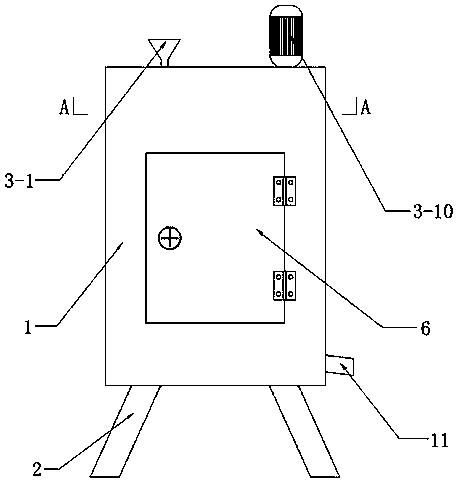
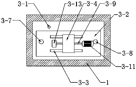
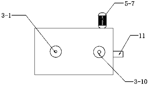
[0026] Such as Figure 1-Figure 6 As shown, this specific embodiment adopts the following technical scheme: it includes a box body 1, a foot 2, a feeding mechanism 3, a fixing mechanism 4, a vibration mechanism 5 and a door body 6, and the four corners of the lower surface of the box body 1 are welded and fixed There are feet 2, and the upper side of the box body 1 is provided with a feeding mechanism 3, and the feeding mechanism 3 is fixed by a feeding pipe 3...


PUM


Abstract

The invention discloses a sand mold casting device for sand core production, and relates to the technical field of sand mold casting equipment. The sand mold casting device comprises a box body, support feet, a feeding mechanism, a fixing mechanism, a vibration mechanism and a door body. The four corners of the lower surface of the box body are fixedly provided with the support feet, the upper side of the inside of the box body is provided with the feeding mechanism, the lower side of the feeding mechanism is provided with the fixing mechanism, the front and rear ends of a fixing plate in thefixing mechanism are slidably arranged on second slide rails in the vibration mechanism through sliders, and the second slide rails on the two sides are fixed to the inner side walls of the front andback sides of the box body. A door body is in screw joint with the interior of an opening in the front side wall of the box body, the right end of the door body is screw joint to the right end of thebox body through a hinge, the left end of the door body is fixedly connected to the left end of the front side wall of the box body through a cross-shaped lock, and a membrane shell is clamped on thefixing mechanism. The fixing mechanism is driven to vibrate by the vibration mechanism, the tightness of pouring materials is increased in the vibration process, so that the membrane shell is fully filled with the pouring materials, core holes existing in casting pieces are reduced, the percent of pass is increased, and the advantages of reasonable arranging, low production cost and the like are achieved.

Description

technical field [0001] The invention relates to the technical field of sand mold casting equipment, in particular to a sand mold casting device for sand core production. Background technique [0002] Sand core is the material used to make the core in foundry production, which is composed of foundry sand, sand binder, etc., while sand mold casting needs to put the finished part model in the sand, and then fill the sand around the model to form a mold , the casting mold is kept for an appropriate time until the metal is solidified. After the part is taken out, the casting mold is destroyed, so a new casting mold must be made for each casting. Conventional sand casting, after the molten pouring material enters the mold, it completely relies on gravity to freely disperse to the film Therefore, it is impossible to ensure that the pouring material is completely filled with the membrane shell. At the same time, there are a large number of sand holes in the casting, and the failure ...

Claims


Application Information

Patent Timeline
Patent Type & Authority Applications(China)
IPC IPC(8): B22D27/08B22D35/04
CPCB22D27/08B22D35/04
Inventor 邓道君王计振肖宇程杨文晶邓忠顺
Owner 溧阳市新明机械配件制造有限公司
Why Eureka
Eureka Blog
Learn More