
Low cost and high performance bolometer circuitry and methods

A technology for measuring bolometers and bolometers, applied to electric radiation detectors, televisions, electrical components, etc., can solve problems such as reducing the available signal range, reducing the sensitivity of bolometer circuits, and introducing noise

Active Publication Date: 2019-12-13
泰立戴恩菲力尔有限责任公司
View PDF25 Cites 4 Cited by
  • Summary
  • Abstract
  • Description
  • Claims
  • Application Information

AI Technical Summary

Problems solved by technology

[0005] Unfortunately, such additional transistors or other control mechanisms in the bolometer conduction path not only increase the size, cost, complexity, and power consumption of conventional bolometer circuits, but also add to the sensitivity of the bolometer circuit. Noise is introduced into the conduction path of the meter
Furthermore, because such additional transistors or other control mechanisms can control the bias by limiting the current and / or voltage on the conduction path of the bolometer, the voltage and / or current that can be used to bias the bolometer is effectively reduced to only a fraction of the supply voltage or current, which in turn reduces the sensitivity of conventional bolometer circuits
Even with this expensive method of bias generation and control, conventional bolometer circuits typically exhibit a reduced usable signal range (e.g., reduced signal swing) for representing IR radiation intensity because due to Changes in environmental and internal conditions (for example, self-heating of the bolometer (also known as pulsed bias heating or pulsed bias heating)) or other factors that need to be allowed to affect the output signal

Method used


Image

  • Low cost and high performance bolometer circuitry and methods
  • Low cost and high performance bolometer circuitry and methods
  • Low cost and high performance bolometer circuitry and methods

Examples


Embodiment Construction

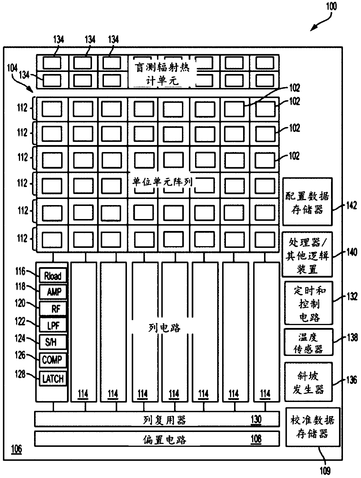
[0058] figure 1 An exemplary bolometer circuit 100 is shown in accordance with an embodiment of the disclosure. The bolometer circuit 100 includes a plurality of active bolometers 102, which may be configured in an array arranged in a rectangular, square, circular, linear, or other shape. In some non-limiting examples, active bolometers 102 may be arranged as a rectangular array having dimensions of 80x60, 160x120, 320x240, or any other size desired for a particular application. The bolometer circuit 100 may include various components and circuits, which may be collectively referred to as a readout integrated circuit (ROIC), that interface with the active bolometer 102 to generate an output as further described herein. A bolometer circuit of some embodiments, such as bolometer circuit 100 , has an active array of bolometers and associated circuitry formed together on a substrate, which may also be referred to as a focal plane array (FPA).

[0059] Portions of the ROIC (eg, s...


PUM


Abstract

A bolometer circuit includes a substrate on which a focal plane array (FPA) of active bolometers is provided. Each active bolometer is configured to receive external infrared (IR) radiation and substantially thermally isolated from the substrate. The bolometer circuit also includes one or more blind arrays of blind bolometers shielded from the external IR radiation and substantially thermally isolated from the substrate. Noises in outputs from each column and / or each row of the FPA are corrected, reduced, or suppressed based on a statistical property of outputs from a corresponding column or row of the one or more blind arrays. Noise in each frame of IR image captured by the FPA may also be corrected, reduced, or suppressed using the one or more blind arrays.

Description

[0001] Cross References to Related Applications [0002] This application claims priority to U.S. Provisional Patent Application No. 62 / 462,321, filed February 22, 2017, entitled "LOW COST AND HIGH PERFORMANCE BOLOMETER CIRCUITRY AND METHODS" and benefit, this Provisional Patent Application is hereby incorporated by reference in its entirety. technical field [0003] One or more embodiments of the invention relate generally to thermal imaging devices, and more particularly, for example, to bolometer circuitry and related processing. Background technique [0004] A bolometer (which changes its electrical resistance in response to optical heating) is often used in the art to detect the intensity of incident infrared (IR) radiation or to capture a multi-pixel IR image of the incident IR radiation intensity. Typically, to measure incident IR radiation, a bias (for example, a bias voltage or current) is applied to the bolometer so that its resistance or any change in it can be m...

Claims


Application Information

Patent Timeline
Patent Type & Authority Applications(China)
IPC IPC(8): H04N5/33H04N5/365H04N5/361
CPCH04N25/677H04N25/672H04N25/21H04N25/76H04N25/633G01J5/22H04N5/33
Inventor R·F·卡纳塔B·B·西蒙朗N·Y·阿齐兹
Owner 泰立戴恩菲力尔有限责任公司
Learn More