
Cooling ring bracket

A cooling ring and bearing ring technology, applied in the direction of pipe support, bearing cooling, rigid support of bearing components, etc., can solve the problems of cooling ring failure, loosening, fasteners, etc., and achieve the possibility of hose damage sex-reducing effect

Active Publication Date: 2019-12-13
SIEMENS GAMESA RENEWABLE ENERGY AS
View PDF7 Cites 0 Cited by
  • Summary
  • Abstract
  • Description
  • Claims
  • Application Information

AI Technical Summary

Problems solved by technology

As mentioned above, the hose is attached to the cooling ring at one point in order to circulate the fluid coolant, but the creeping movement of the cooling ring can eventually lead to failure at the hose connection point
A cold weld is more likely to form between two objects made of the same metal, but even if the bracket is made of a metal different from that of the cooling ring to avoid the formation of a cold weld, this will not solve the problem of loose fasteners The problem

Method used


Image

  • Cooling ring bracket
  • Cooling ring bracket
  • Cooling ring bracket

Examples


Embodiment Construction

[0034] In the figures, like numerals refer to like objects throughout. Objects in the drawings are not necessarily drawn to scale.

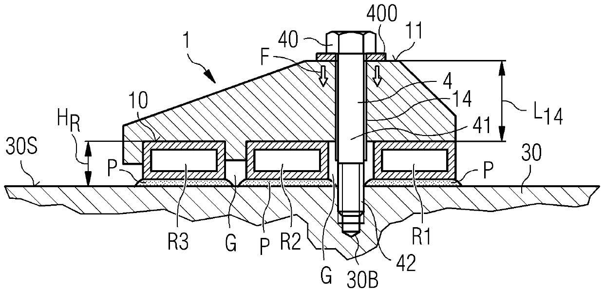
[0035] figure 1 An embodiment of a stent 1 of the invention is shown. The support 1 is formed in one piece, eg by injection molding, and is realized extending across three parallel cooling rings R1 , R2 , R3 . The main body of the bracket 1 is roughly in the shape of an acute trapezoid, and its highest point is located above the gap G between two adjacent cooling rings R1, R2. The stand 1 extends substantially from the base level 10 to the upper level 11 and its shape is defined by inclined sides extending from the base level 10 to the upper level 11 . The stent is made from a highly resilient material that also exhibits a favorable degree of elasticity and resiliency, allowing it to assume its original shape after being compressed. A suitable choice of material may be a high performance engineering polymer such as polyoxymethylene (POM-C) du...


PUM


Abstract

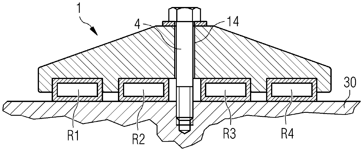
The invention relates to a cooling ring bracket, and describes a bracket (1) for securing a number of cooling rings (R1, R2, R3) arranged on a bearing ring (30), which bracket (1) comprises an upper surface (11), a lower surface (10) shaped to lie on the cooling rings (R1, R2, R3), and a through-opening (14) extending between the upper surface (11) and the lower surface (10) to accommodate a fastener (4) for mounting the bracket (1) to the bearing ring (30); wherein the material properties of the bracket (1) are chosen to permit movement of the cooling rings (R1, R2, R3) relative to the bracket (1) when the bracket (1) is mounted to the bearing ring (30); and / or wherein the bracket (1) is made of a resilient elastic material. The invention further describes a cooling arrangement (2) for abearing (3), comprising a number of cooling rings (R1, R2, R3) arranged in parallel on a mounting surface (30S) of a bearing ring (30) of the bearing (3); and a number of such brackets (1) to secure the cooling rings to the bearing body (30).

Description

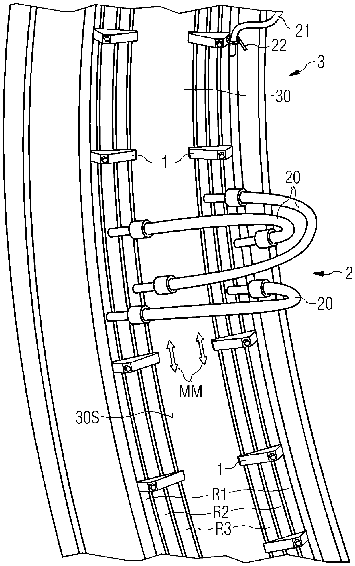
technical field [0001] The present invention describes cooling ring supports and cooling arrangements. Background technique [0002] Large bearings are necessary in various applications such as large electric motors. Main bearings of generators such as multi-megawatt wind turbine generators may have a diameter of several meters. During operation, the rotating bearing ring turns relative to the stationary bearing ring, and it is often unavoidable to generate heat during operation, so large bearings require some kind of cooling arrangement. [0003] One way of cooling such a large bearing is to arrange a number of hollow annular passages or "cooling rings" around the stationary bearing ring and to feed a fluid cooling medium through these passages. The cooling circuit is completed by connecting the cooling ring by means of hoses to a pump which circulates a fluid coolant through the channels. Thermal paste can be applied between the bearing surface and the cooling ring to i...

Claims


Application Information

Patent Timeline
Patent Type & Authority Applications(China)
IPC IPC(8): F16C37/00F16C35/00
CPCF16C37/00F16C35/00F28D2021/0029F28F1/04F28F9/013F28F2275/08F28F2275/20F03D15/20F03D80/60F03D80/70F05B2240/50F05B2260/30F16C37/007F16C2300/14F16C2360/31F16L3/04F16L3/2235Y02E10/72F16C33/586F16C33/64F16C43/04F16C2226/76F16C2300/54
Inventor T.奎斯特
Owner SIEMENS GAMESA RENEWABLE ENERGY AS
Learn More