


Quick Research
Generate reliable direction feasibility study reports for your R&D in just a few steps.

Technical Q&A
Discover and master advanced knowledge NOW. Basics, ideas, possibilities, all at once.

Find Solutions
As an expert in R&D theories, this can generate solutions to your technical problems instantly.

Evaluate Feasibility
Analyze your overall solution with one click, know your potential R&D risks in advance.

Monitor Landscape
Get weekly tech updates, stay abreast of the latest tech innovations and key insights.
Novel buckle strip
A buckle, a new type of technology, applied in the direction of floors, buildings, building structures, etc., can solve the problems of increasing the overall thickness, large thickness, and affecting the appearance, and achieve the effect of overcoming technical contradictions and preventing wear and tear
- Summary
- Abstract
- Description
- Claims
- Application Information
AI Technical Summary
Problems solved by technology
Method used
Image

Examples
Embodiment 1
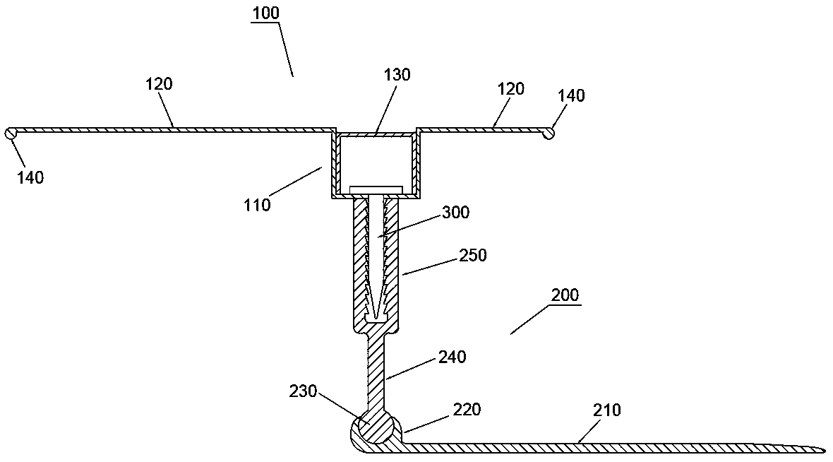
[0026] Example 1: Reference figure 1 A new type of buckle shown is a transitional buckle, which is used for the transition between pavement surfaces and pavement surfaces, and includes a bead structure 100 and a fixing structure 200 . The bead structure 100 includes a sinking groove 110, bead parts 120 arranged on both sides of the sinking groove 110, and a cover strip 130 arranged in the sinking groove 110. The bead structure 100 is installed on the fixed structure 200 through the bottom of the sinking groove 110 . Wherein, the sinking groove 110 and the bead part 120 are formed by folding a whole strip metal plate, and the bead part 120 is a straight strip metal part after being folded, so that the decoration formed by the bead part 120 on both sides All surfaces are flat.
[0027] By means of the above structure, by designing the bead part 120 as a straight strip metal piece, so that the decorative surface formed by it is a plane, when it adopts the material thickness equ...
Embodiment approach
[0031] In some embodiments, the fixing structure 200 can be any implementation in the prior art for fixing the bead structure 100, for example, the fixing structure 200 can be a bolt seat and a bolt, directly through the cooperation of the bolt seat and the bolt The bead structure 100 is fixed on the fixed structure 200, and then fixed on the ground. It is also possible to use the matching structure of the injection screw and the movable joint in the patent CN201010146541.7. For another example, a screw hole is provided on the bottom surface of the sinking tank 110 , and a fixing nail 300 is disposed through the screw hole, and the bead structure 100 and the fixing structure 200 are connected by the fixing nail 300 . The fixing nail 300 can be a nail or a screw, and in this embodiment, the fixing nail 300 is a screw.
[0032] In particular, in this embodiment, the fixing structure 200 includes a fixed base 210, a partial ring sleeve 220 fixedly arranged on the fixed base 210,...
Embodiment 2
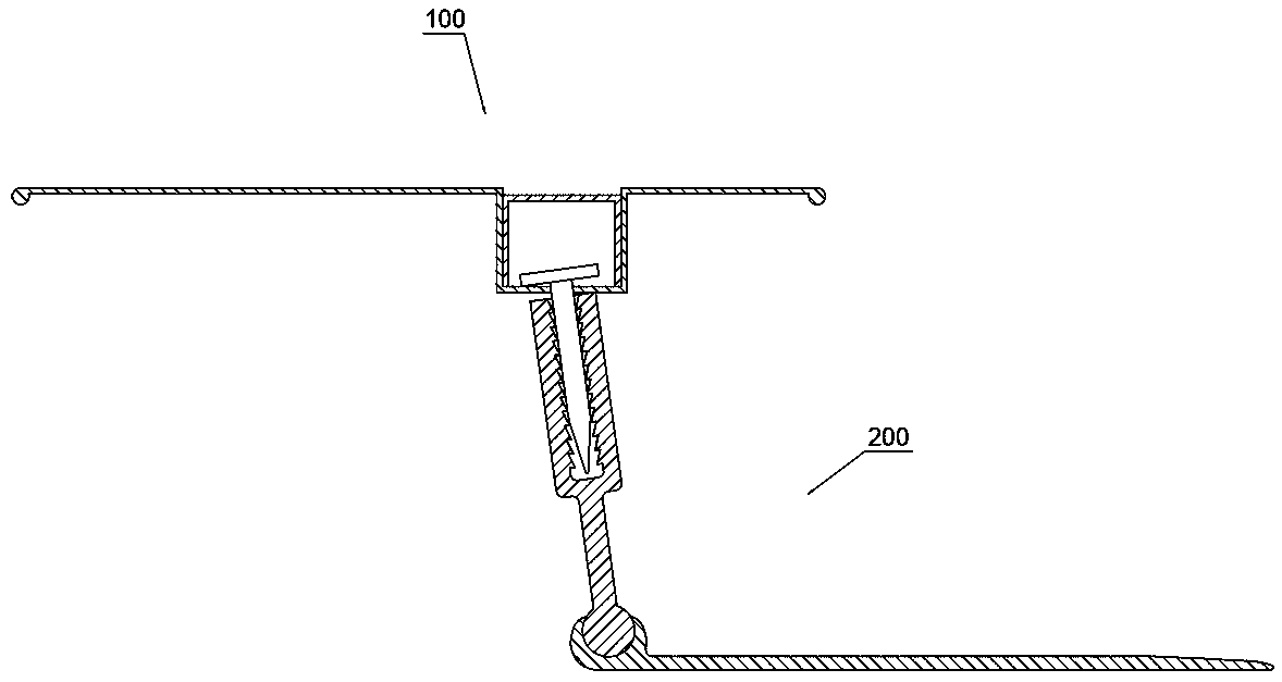
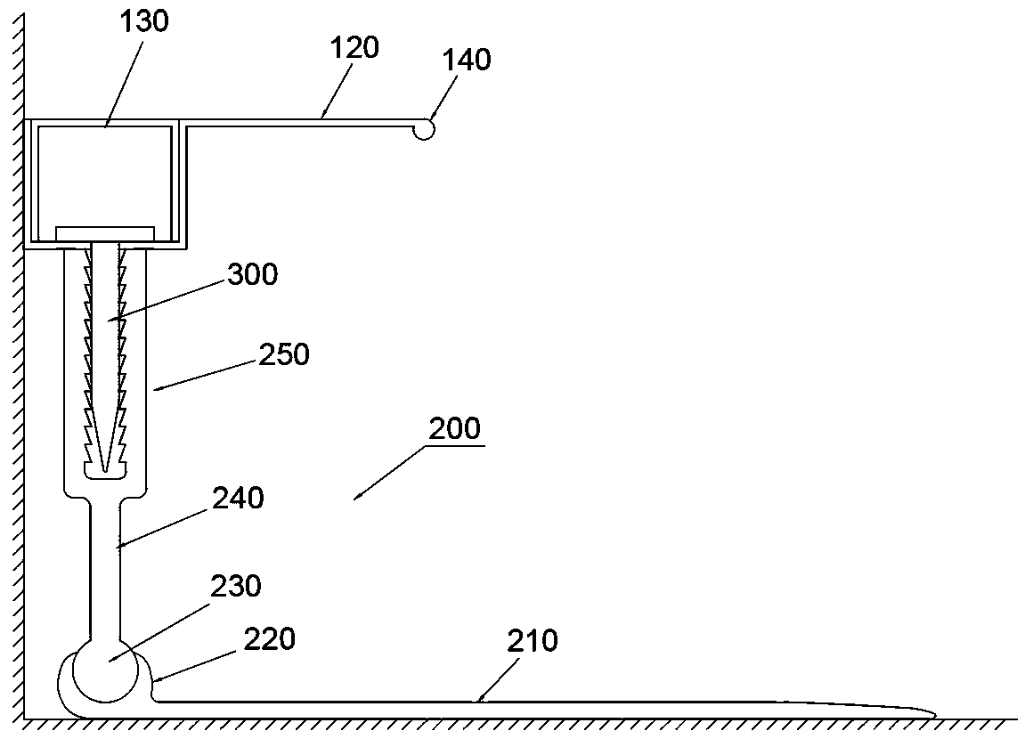
[0034] Embodiment 2: the difference between embodiment 2 and embodiment 1 is that, refer to image 3 Shown is a trim profile for transition between pavement and fixed wall. The bead portion 120 is only provided on one side of the sinking tank 110 . Thus, compared to Figure 4 The edge-receiving buckle of the prior art shown can completely abut against the fixed wall, and there is no gap D between the fixed wall and the fixed wall.
PUM
 Abstract
Description
Claims
Application Information
 - R&D Engineer
- R&D Manager
- IP Professional
- Industry Leading Data Capabilities
- Powerful AI technology
- Patent DNA Extraction
Browse by: Latest US Patents, China's latest patents, Technical Efficacy Thesaurus, Application Domain, Technology Topic, Popular Technical Reports.
© 2024 PatSnap. All rights reserved.Legal|Privacy policy|Modern Slavery Act Transparency Statement|Sitemap|About US| Contact US: help@patsnap.com