


Quick Research
Generate reliable direction feasibility study reports for your R&D in just a few steps.

Technical Q&A
Discover and master advanced knowledge NOW. Basics, ideas, possibilities, all at once.

Find Solutions
As an expert in R&D theories, this can generate solutions to your technical problems instantly.

Evaluate Feasibility
Analyze your overall solution with one click, know your potential R&D risks in advance.

Monitor Landscape
Get weekly tech updates, stay abreast of the latest tech innovations and key insights.
Noise reduction structure for air-cooled heat pump and cooling tower and its construction technology
An air-cooled heat pump and cooling tower technology, applied in the field of noise reduction, can solve the problems of hindering air flow, affecting the normal operation of the air-cooled heat pump and cooling tower, etc., and achieves the effect of increasing the connection strength, the sound insulation effect is not easy, and the deformation is not easy.
- Summary
- Abstract
- Description
- Claims
- Application Information
AI Technical Summary
Problems solved by technology
Method used
Image

Examples
Embodiment 1
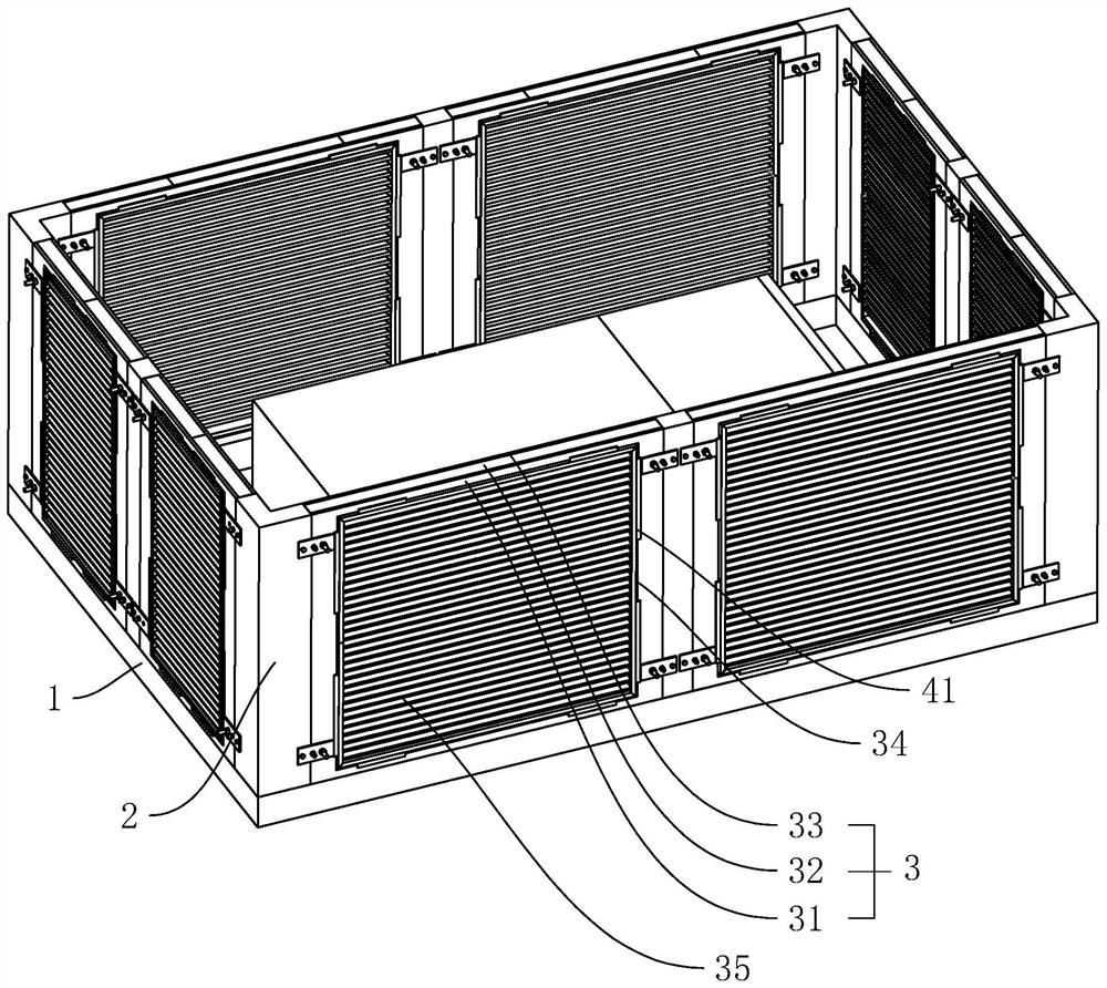
[0041] Embodiment 1: as figure 1 As shown, it is an air-cooled heat pump and cooling tower noise reduction structure disclosed by the present invention, which includes columns 2 arranged around the equipment and sound insulation boards 3 arranged between the columns 2, and the ground is poured with 10cm-20cm high The base 1 and the column 2 are fixed on the upper end of the base 1 with expansion bolts, the vertical side wall of the sound insulation board 3 is in contact with the column 2 , and the lower end of the sound insulation board 3 is in contact with the upper end of the base 1 . The end surface of the sound insulation board 3 close to the equipment is penetrated with flow holes 34 , and sound-absorbing louvers 35 are arranged in the flow holes 34 . The sound insulation board 3 comprises a steel plate 31 with a thickness of 15mm, a centrifugal glass wool 32 with a thickness of 100mm and a perforated galvanized sheet 33 with a thickness of 6mm arranged in sequence. The ...
Embodiment 2
[0049] Embodiment 2: A kind of construction technique of the noise reduction structure of air-cooled heat pump and cooling tower, comprises the following steps:
[0050] S1: Pour a base 1 with a height of 10cm-20cm around the equipment, wait for the base 1 to solidify and install the column 2 on the upper end of the base 1 with expansion bolts;
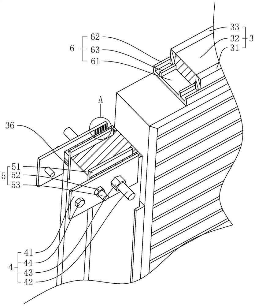
[0051] S2: Measure the distance between the columns 2 and cut the sound insulation board 3 according to the size, and cut out the flow hole 34 in the middle of the sound insulation board 3, and cut out the two ends of the steel plate 31 and the perforated galvanized board 33 which are vertically arranged Several receiving grooves 36;
[0052] S3: Insert the reinforcing plate 51 between the steel plate 31 and the multi-hole galvanized plate respectively, and place the reinforcing screw 52 in the receiving groove 36, and then use a press to apply pressure to the reinforcing plate 51 and the connecting plate 41 at the same time to make t...
PUM
 Abstract
Description
Claims
Application Information
 - R&D Engineer
- R&D Manager
- IP Professional
- Industry Leading Data Capabilities
- Powerful AI technology
- Patent DNA Extraction
Browse by: Latest US Patents, China's latest patents, Technical Efficacy Thesaurus, Application Domain, Technology Topic, Popular Technical Reports.
© 2024 PatSnap. All rights reserved.Legal|Privacy policy|Modern Slavery Act Transparency Statement|Sitemap|About US| Contact US: help@patsnap.com