Image reader
A reader and image technology, applied in the direction of image communication, electrical components, etc., can solve the problems of low adaptability and inability to read multiple images continuously
- Summary
- Abstract
- Description
- Claims
- Application Information
AI Technical Summary
Problems solved by technology
Method used
Image
Examples
Embodiment approach 9
[0500] The description of Embodiment Mode 9 has assumed a case where data communication is performed through one cable 905, but data communication can be performed through wireless communication. This wireless communication for this purpose includes microwave communication, optical communication, infrared communication or the like. When using this microwave communication, an antenna and a transmitter / receiver for transmitting and receiving microwaves are provided instead of the communication control section 901 shown in FIG. 24, and a similar antenna is also provided in the computer 903 And transmitter / receiver. With this structure, the computer 903 and the image data storage 701 are connected to each other through a microwave line.
[0501] When an optical communication is adopted, an optical transmitter / receiver having a light emitting part for emitting light and a light receiving part for receiving light is provided instead of the communication control section 901 shown in FIG. 2...
Embodiment approach 17
[0854] (First example of operation of embodiment 17)
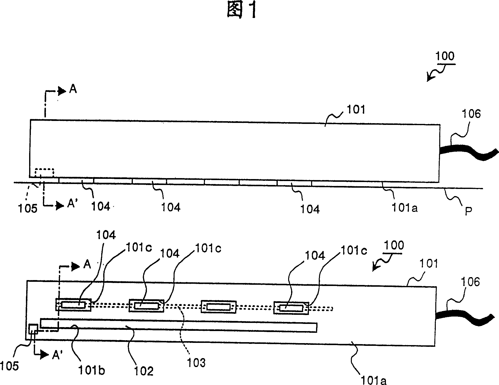
[0855] An example of the operation of the image reader 2150 according to Embodiment 17 will be described below with reference to a flow chart of FIG. 86. Assume that the reading of an image is affected after a power switch that is not displayed is turned on, and it is assumed that the image reader 2150 (document detection section 105) shown in FIG. 85 is not close to a document. Then, in step SN1 shown in FIG. 86, the reading control section 2152 reports to the user that the image can be read by turning on a lamp or the like, and then the system control goes to step SN2.
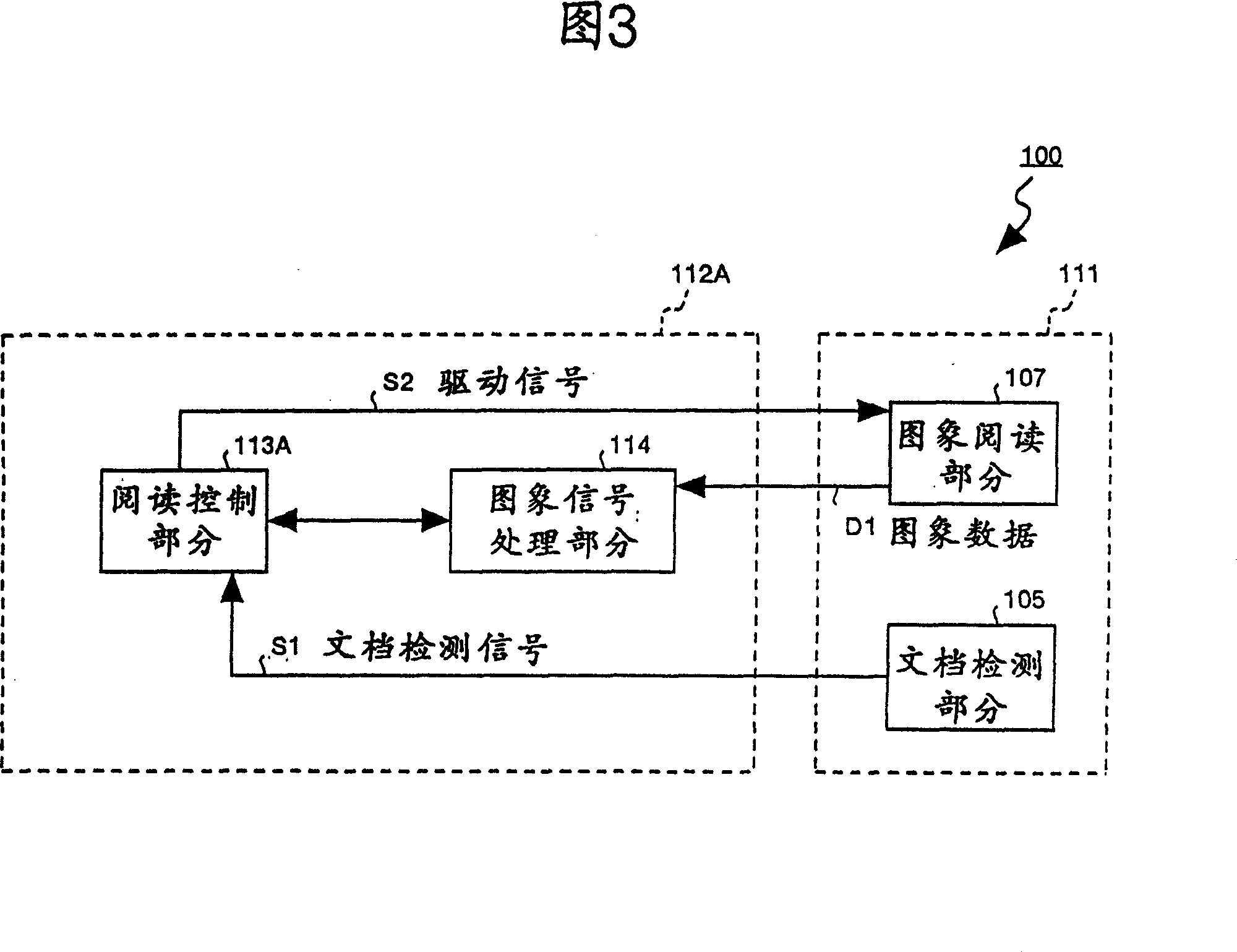
[0856] In step SN2, the reading control section 2152 enables the input reception of a document detection signal S1 from the document detection section 105, and then the system control goes to step SN3. Here, the document detection signal S1 is a signal output from the document detection section 105 when a document touches (tightly touches) the image reading ...
PUM
 Abstract
Description
Claims
Application Information
 - Generate Ideas
- Intellectual Property
- Life Sciences
- Materials
- Tech Scout
- Unparalleled Data Quality
- Higher Quality Content
- 60% Fewer Hallucinations
Browse by: Latest US Patents, China's latest patents, Technical Efficacy Thesaurus, Application Domain, Technology Topic, Popular Technical Reports.
© 2025 PatSnap. All rights reserved.Legal|Privacy policy|Modern Slavery Act Transparency Statement|Sitemap|About US| Contact US: help@patsnap.com


