
Steel grid ring type wind power tower base ring facility and construction method

A steel grid and foundation ring technology is applied in the construction field of steel grid ring wind power tower foundation ring facilities, which can solve the problems of not considering the force form of the wind turbine foundation, and achieve improved bonding effect, simple construction, and high efficiency. The effect of security

Pending Publication Date: 2019-12-13
LANZHOU UNIVERSITY OF TECHNOLOGY
View PDF0 Cites 2 Cited by
  • Summary
  • Abstract
  • Description
  • Claims
  • Application Information

AI Technical Summary

Problems solved by technology

[0004] Most of the current fan foundation design is based on similar design experience from previous engineering examples, without considering the special force form of the fan foundation

Method used


Image

  • Steel grid ring type wind power tower base ring facility and construction method
  • Steel grid ring type wind power tower base ring facility and construction method
  • Steel grid ring type wind power tower base ring facility and construction method

Examples


Embodiment 1

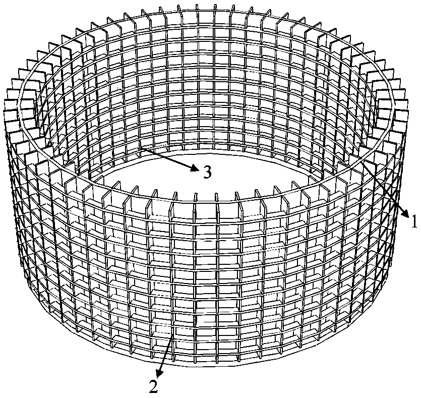
[0031] like figure 1 As shown, the steel grid ring type wind power tower base ring facility of the present invention includes a fan base ring 1 with a flange plate, an outer steel grid ring 2 and an inner steel grid ring 3 .

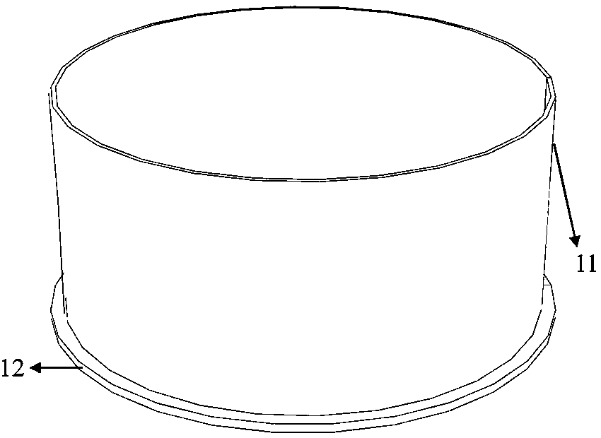
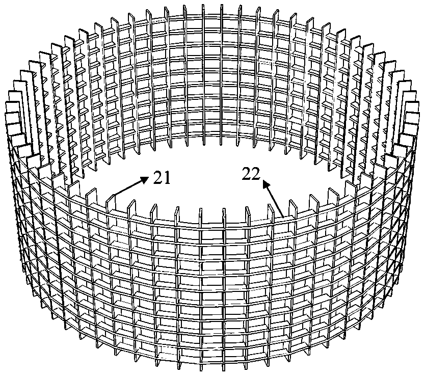
[0032] like figure 2 , Figure 5 , Image 6 As shown, the basic ring 1 of the fan with flange plate includes the basic ring 11 of the fan and the flange plate 12, and the basic ring 11 of the fan is welded to the upper end of the flange plate 12; image 3 , 7 As shown in ~9, the outer steel grating ring 2 includes the vertical steel grating strip group 21 of the outer ring, the horizontal steel grating plate group 22 of the outer ring, and the horizontal steel grating plate group 22 of the outer ring is sequentially inserted into the outer ring according to the direction of the outer ring. Circle the reserved rectangular holes of the vertical steel grating bar group 21, and weld and seal the reserved rectangular holes; Figure 4 , 10 As shown in ~...

Embodiment 2

[0047] like Figure 14As shown, the difference between this embodiment and Embodiment 1 is that: the base ring of the fan is a double-layer steel pipe; the reserved holes of the vertical steel grid strip group of the outer ring are reserved oblong holes; The reserved holes facing the steel grid bar group are reserved oblong holes; the outer ring horizontal steel grid plate group is the outer ring ribbed steel mesh; the inner ring horizontal steel grid plate group is the inner ring strip Ribbed steel mesh. The rest of the structures and connections in this embodiment are the same as those in Embodiment 1.

Embodiment 3

[0049] like Figure 15 As shown, the difference between this embodiment and Embodiment 1 is that: the foundation ring of the fan is a hollow interlayer concrete filled steel pipe; the reserved holes of the vertical steel grid strip group of the outer ring are reserved oblong holes; the inner ring The reserved holes of the vertical steel grid bar group are reserved oblong holes; the outer ring horizontal steel grid plate group is the outer ring cold-rolled twisted steel mesh; the inner ring horizontal steel grid plate group is the outer Ring cold rolled twisted steel mesh. The rest of the structures and connections in this embodiment are the same as those in Embodiment 1.


PUM


Abstract

The invention provides a steel grid ring type wind power tower base ring facility and a construction method. A fan base ring with a flange plate comprises a fan base ring body and the flange plate. The fan base ring body is welded to the upper end of the flange plate. An outer steel grid ring comprises an outer ring vertical steel grid strip group and an outer ring horizontal steel grid plate group. The outer ring horizontal steel grid plate group is sequentially inserted into reserved rectangular holes of the outer ring vertical steel grid strip group in the direction of an outer ring, and the reserved rectangular holes are welded and sealed; and an inner steel grid ring comprises an inner ring vertical steel grid strip group and an inner ring horizontal steel grid plate group. The innerring horizontal steel grid plate group is sequentially clamped into reserved rectangular holes of inner ring vertical steel grid strip group in the direction of an inner ring, and the reserved rectangular holes are welded and sealed. The construction method comprises the steps that the fan base ring with the flange plate is welded, the outer ring vertical steel grid strip group is welded, the inner ring vertical steel grid strip group is welded, the outer ring horizontal steel grid plate group is installed, and the inner ring horizontal steel grid plate group is installed. The defects of an existing base ring are overcome, and the anti-slip performance is improved.

Description

technical field [0001] The invention relates to structural engineering technology, in particular to the construction technology of steel grid ring type wind power tower foundation ring facilities. Background technique [0002] As the foundation guarantee for the smooth operation of the entire wind power generation system, the foundation of the wind power generation unit not only bears the vertical load brought by the upper tower of the unit and the weight of the power generation structure, but also bears the dynamic action from the rotation of the wind turbine blades driven by the wind and the earthquake. With the development of the wind power industry, high-power wind turbines continue to appear. Large-capacity wind turbines need to obtain greater wind energy at a higher position. Now the diameter of the wind turbine blade reaches 800~100m. With the continuous increase of the blade diameter, the load on the foundation Also getting bigger and bigger. And with the continuous...

Claims


Application Information

Patent Timeline
Patent Type & Authority Applications(China)
IPC IPC(8): E02D27/42
CPCE02D27/425
Inventor 王文达郑龙史艳莉范家浩陈振福纪孙航
Owner LANZHOU UNIVERSITY OF TECHNOLOGY
Learn More