
Dry slag discharge fluidized bed gasification reaction device

A technology for fluidized bed gasification and dry slagging, which is applied in the field of coal gasification and can solve the problems of expensive materials, high repair and maintenance costs, and increased production costs.

Active Publication Date: 2021-05-18
ANHUI UNIV OF SCI & TECH
View PDF12 Cites 0 Cited by
  • Summary
  • Abstract
  • Description
  • Claims
  • Application Information

AI Technical Summary

Problems solved by technology

Under such operating conditions, the slag discharge pipe is exposed to harsh working conditions such as high temperature and high pressure and molten ash adhesion for a long time, which seriously affects the service life of the slag discharge pipe. Therefore, it must be replaced or repaired frequently. Due to the expensive materials used, High repair and maintenance costs, and frequent shutdowns lead to a substantial increase in production costs
[0003] According to the existing industrial application and operation of fluidized bed gasification, it is found that the carbon conversion rate of fluidized bed gasification technology has been relatively low because its reaction temperature is lower than the melting point of fuel ash, and its residence time is lower than that of fixed bed. Low level, hard to reach 99% carbon conversion level for entrained and fixed bed gasification reactors

Method used


Image

  • Dry slag discharge fluidized bed gasification reaction device
  • Dry slag discharge fluidized bed gasification reaction device
  • Dry slag discharge fluidized bed gasification reaction device

Examples


Embodiment Construction

[0034] The present invention will be further explained below in conjunction with specific embodiments.

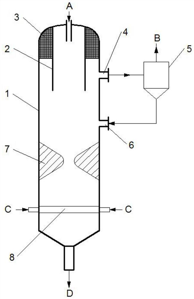
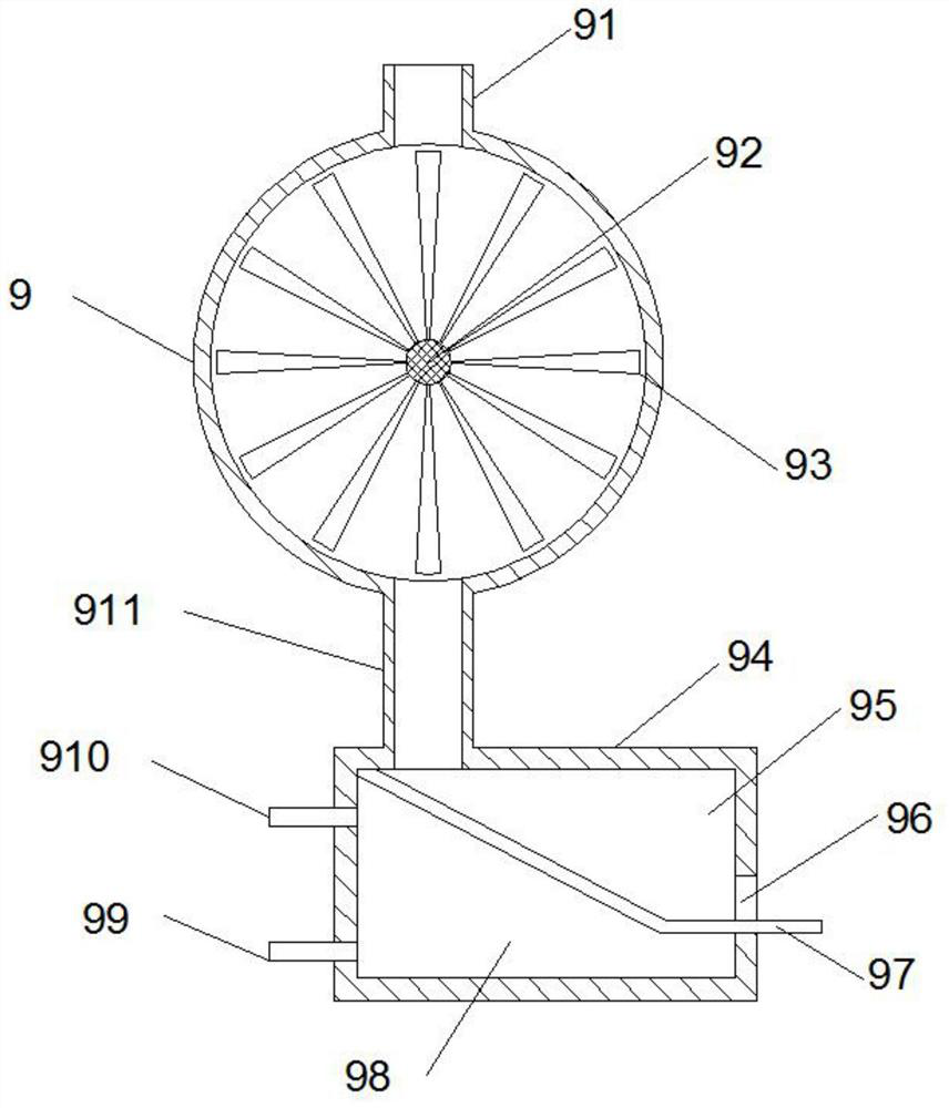
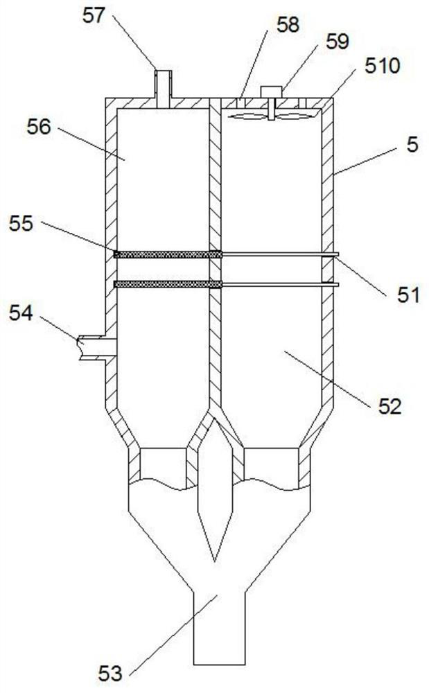
[0035] refer to Figure 1-5 , the dry slagging fluidized bed gasification reaction device proposed by the present invention includes an outer casing, the top wall of the outer casing is fixed with an inner cylinder opening downward, and the top wall of the outer casing is also provided with a A feed opening in the inner space of the inner cylinder, a distributor and a gasification agent inlet connected to the distributor are provided at the lower end of the inner cavity of the outer shell, and a slag discharge port is provided at the bottom of the outer shell, and the slag discharge port A slagging system is connected, and an exhaust port is provided on the side wall of the outer casing, and a filter system is connected to the exhaust port. The material enters the shell from the feed port, and the material is gasified by high temperature and gasification agent sprayed from...


PUM


Abstract

The invention discloses a dry slag discharge fluidized bed gasification reaction device, which comprises an outer casing, the top wall of the outer casing is fixed with an inner cylinder opening downward, and the top wall of the outer casing is also provided with a There is a feed port opening in the inner space of the cylinder, a distributor and a gasification agent inlet connected to the distributor are provided at the lower end of the inner cavity of the outer shell, and a slag discharge port is provided at the bottom of the outer shell, and the slag discharge port is connected to There is a slagging system, the side wall of the outer shell is also provided with an exhaust port, the exhaust port is connected with a filter system, the slag discharging system includes a rotating hopper and a cooling room, and the rotating hopper includes a The rotating shaft is provided with several impellers, and the rotating shaft is electrically connected to the driving device located outside the rotating hopper, the upper end of the rotating hopper is provided with a hopper inlet, and the lower end of the rotating hopper is provided with a hopper outlet. The invention improves the carbon conversion rate, and improves operation and running stability.

Description

technical field [0001] The invention relates to the technical field of coal gasification, in particular to a dry slag discharge fluidized bed gasification reaction device. Background technique [0002] The premise of the semi-dry method of ash fusion and slag discharge is to form a local high-temperature zone in the reactor, and at the same time form an agglomeration flow field, so that the particles collide and bond with each other and then discharge through the ring-shaped slag discharge pipe. Under such operating conditions, the slag discharge pipe is exposed to harsh working conditions such as high temperature and high pressure and molten ash adhesion for a long time, which seriously affects the service life of the slag discharge pipe. Therefore, it must be replaced or repaired frequently. Due to the expensive materials used, Repair and maintenance costs are high, and frequent shutdowns lead to a significant increase in production costs. [0003] According to the existi...

Claims


Application Information

Patent Timeline
Patent Type & Authority Patents(China)
IPC IPC(8): C10J3/56C10J3/72C10J3/84
CPCC10J3/56C10J3/72C10J3/84C10J2200/09C10J2300/0956C10J2300/0959C10J2300/0966C10J2300/0976
Inventor 纪明俊李寒旭武成利高圣涛
Owner ANHUI UNIV OF SCI & TECH
Learn More