Powdered-coal burner and rotary cement kiln using same
A technology of pulverized coal burner and cement rotary kiln, which is applied in the direction of burner, burner, and combustion method of burning powder fuel, and can solve the problems of unable to prevent the mixing of pulverized coal secondary air, complex fluid working conditions, and limited effect , to improve the service life, simplify the structure and increase the temperature
- Summary
- Abstract
- Description
- Claims
- Application Information
AI Technical Summary
Problems solved by technology
Method used
Image
Examples
Embodiment 1
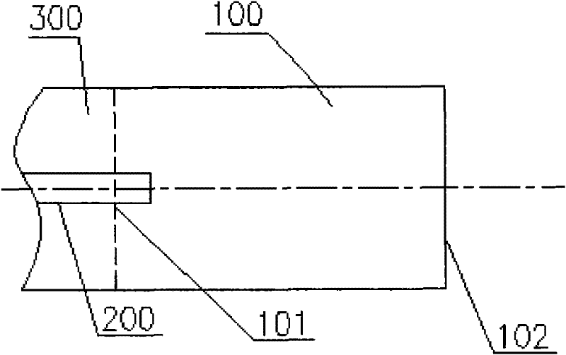
[0046] Please refer to figure 2 , which is a schematic structural view of the pulverized coal burner provided in Embodiment 1. The pulverized coal burner includes a fire source 200 and an internal combustion chamber 100. The internal combustion chamber 100 has a feed inlet 101 and a fire outlet 102, and a combustion section is formed between the feed inlet 101 and the fire outlet 102. In this example, the pulverized coal burner further includes a transition duct 300 which communicates with the pulverized coal duct, and the fire source 200 extends from the transition duct 300 into the internal combustion chamber 100 .
[0047] The transition pipe 300 communicates with the combustion section through the feed port 101 to introduce pulverized coal into the combustion section. In the direction of the pulverized coal flow, the internal combustion chamber 100 has a reasonable length and cross-sectional area, and can maintain the internal pulverized coal flow with a predetermined ex...
Embodiment 2
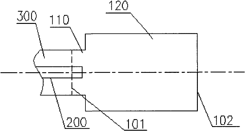
[0055] Please refer to image 3 , which is a schematic structural view of the pulverized coal burner provided in Embodiment 2. Based on the first embodiment, the internal combustion chamber 100 includes a combustion section 120 and an enlarged inlet section 110 connected to the front end of the combustion section 120 , and the feed port 101 is located at the intersection of the enlarged inlet section 110 and the transition duct 300 . As shown, the cross-sectional area of the inlet amplification section 110 is smaller than the cross-sectional area of the combustion section 120 . When the pulverized coal enters the combustion section 120 with a larger cross-sectional area from the inlet enlargement section 110 with a smaller cross-sectional area, the flow velocity of the pulverized coal will decrease accordingly. In this way, under the condition that the length of the internal combustion chamber 100 does not change, the pulverized coal with a low flow rate needs a longer ti...
Embodiment 3
[0060] It can be understood that when the pulverized coal ignited in the internal combustion chamber 100 enters the calcining chamber of the cement rotary kiln through the fire outlet 102 in the form of a pulverized coal flame, in order to make the pulverized coal flame have higher rigidity, the flow velocity of the pulverized coal flame To adapt to the overall combustion structure of the calcining chamber of the cement rotary kiln, an outlet narrowing section can also be provided in the internal combustion chamber 100 . Such as Figure 5 As shown, this figure shows a schematic structural view of the pulverized coal burner provided by Embodiment 3, which also has an outlet narrowing section 130 connected to the rear end of the combustion section 120; also in order to ensure that the pulverized coal flame velocity changes Relative stability at the time, in the flow direction of the pulverized coal flame, the cross-sectional area of the outlet narrowing section 130 gradually d...
PUM
 Abstract
Description
Claims
Application Information
 - R&D
- Intellectual Property
- Life Sciences
- Materials
- Tech Scout
- Unparalleled Data Quality
- Higher Quality Content
- 60% Fewer Hallucinations
Browse by: Latest US Patents, China's latest patents, Technical Efficacy Thesaurus, Application Domain, Technology Topic, Popular Technical Reports.
© 2025 PatSnap. All rights reserved.Legal|Privacy policy|Modern Slavery Act Transparency Statement|Sitemap|About US| Contact US: help@patsnap.com


