A cross-air lift

A technology of the main frame and vertical guide rails, which is applied in the field of moving ladders across the air, which can solve the problems of long walking distance, inconvenience to the disabled, physical exertion, etc., achieve low manufacturing and maintenance costs, save time and energy, and occupy a small area Effect

Active Publication Date: 2021-08-24
陈世记
View PDF7 Cites 0 Cited by
  • Summary
  • Abstract
  • Description
  • Claims
  • Application Information

AI Technical Summary

Problems solved by technology

[0004] In view of the above technical problems, the embodiment of the present invention provides a high-efficiency, fast, easy-to-use and easy-to-use air-span moving ladder, which can directly transport pedestrians from one side of the road to the other side, so as to solve the problem of the long walking distance of existing human-shaped overpasses. , time-consuming, labor-intensive, and inconvenient for the disabled and pedestrians with walking difficulties

Method used


Image

  • A cross-air lift
  • A cross-air lift
  • A cross-air lift

Examples


Embodiment 1

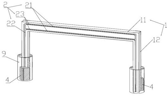
[0039] like Figure 1-5 A span ladder, including the body frame 1 for across the pavement, the carrier operating system provided along the body frame, including the beam 11 and a column 12 of the side of the beam , Overall in pouring U-shaped structure.

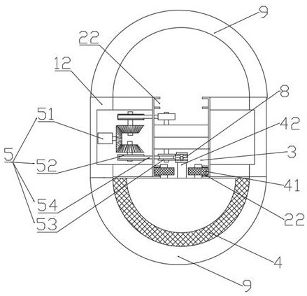
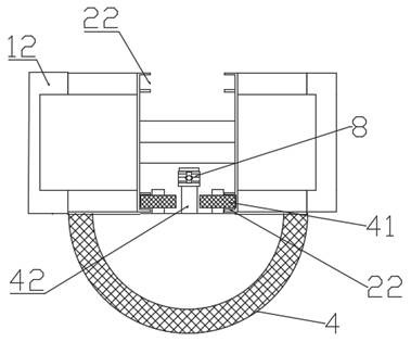
[0040] The manned operating system includes a sliding guide rail 2 on the main body frame, a traction rail 3, a carrier-to-manned carrier 4 and a traction mechanism 5 operated along the slide guide rail. The sliding guide rail 2 is located on the U-shaped side of the main body frame, extends from one end of the main body frame 1 to the other end, which is horizontally guide rail 21, two vertical rails 22 on both sides of the horizontal guide rail, and the cohesal horizontal guide rail 21 and vertical rail 22 of the arc guide rail 23 constitutes. The various segments of the traction rail 3 are arranged in parallel along three rails of the sliding guide rail 2, respectively.

[0041] The back surface of the manned cell 4 is provided...

Embodiment 2

[0055] In this embodiment, on the basis of Example 1, the flexible member is replaced with a chain traction mechanism, with the traction sheave, to engage the guide wheel type transmission, guide wheels and the traction wheel gear. Such higher traction mechanism transmission efficiency, more stable, higher cost.

[0056] Two manned operation of the system are independently driven by respective traction mechanism 5, two cabins were small manned operate independently under the action of a respective manned operation of the system. Two-wheel drive traction machine manned operation of the system, the drive connection thereto are provided at the bottom of the two columns of the lumen, the inner cavity structure only make full use of the two uprights, the uprights and the narrow area, it more popular. Provided independently of the two manned operation of the system, but also improve the flexibility of both manned operation of the system.

[0057] In order to improve performance stabilit...


PUM


Abstract

The invention discloses an air-span moving ladder, which comprises a main frame for crossing both sides of the road surface and a manned running system arranged along the main frame, the main frame includes a beam and columns fixed on both sides of the beam, the The manned running system includes a sliding guide rail on the main frame, a traction guide rail, a manned cabin running along the sliding guide rail, and a traction mechanism; the sliding guide rail is located on the side of the main frame, which includes horizontal guide rails, Two vertical guide rails, and an arc-shaped guide rail connecting the horizontal guide rail and the vertical guide rail; the back of the manned cabin is provided with a pulley block that cooperates with the sliding guide rail and a traction connector connected with the traction mechanism, and the traction mechanism drives the manned cabin along the Run along the sliding guide rail from the bottom of one column to the bottom of the other column. The above-mentioned air-crossing ladder has a compact structure and a small footprint, enabling pedestrians to quickly and conveniently cross from one side of the space to the other, and is also convenient for the disabled and pedestrians with walking disabilities to pass.

Description

Technical field [0001] The present invention relates to the field of elevator technologies, and more particularly to a span empty shock. Background technique [0002] At present, urban road pedestrians and vehicle disputes have seriously affected the vehicle pass speed and bring serious personal safety threats, and the crowd of important intersections, not only exacerbating traffic jam, but also gives a lot of inconvenience, such as Waiting for the long time of traffic, there is a safe hidden danger, and it does not apply to the elderly with disabled people and the inconvenience. In addition, the railway and highways are more long-distance unable to pass. Although the existing human bridge solves the above problems to some extent, the existing pedestrian bridge covers an area, but also greatly extended the distance of pedestrians, but not only time, consuming physical strength, and not convenient for disabled people and Pedestrians who walk away. [0003] Therefore, the prior art...

Claims


Application Information

Patent Timeline
Patent Type & Authority Patents(China)
IPC IPC(8): B66B9/00B66B11/08
CPCB66B9/003B66B11/0095
Inventor 曾智勇
Owner 陈世记
Why Eureka
Try Eureka