A cooling cycle system

A circulatory system and cooling technology, applied in refrigerators, refrigeration components, refrigeration and liquefaction, etc., to achieve high safety, simple and compact structure, and efficient operation.

Active Publication Date: 2021-09-17
TECHNICAL INST OF PHYSICS & CHEMISTRY - CHINESE ACAD OF SCI
View PDF6 Cites 0 Cited by
  • Summary
  • Abstract
  • Description
  • Claims
  • Application Information

AI Technical Summary

Problems solved by technology

Due to the reliability of the cryogenic pump, the traditional method of cryogenic pumping of brine has a great risk in the application process

Method used


Image

  • A cooling cycle system
  • A cooling cycle system
  • A cooling cycle system

Examples


Embodiment 1

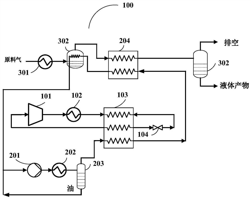
[0026] see figure 1 , is a schematic structural diagram of a load-cooling cycle system provided by Embodiment 1 of the present invention. For the convenience of description, only the parts related to the embodiment of the present invention are shown, and the details are as follows.

[0027]The load cooling cycle system 100 provided by the present invention includes: a mixed working medium refrigeration cycle circuit and a load cooling cycle circuit; the mixed working medium refrigeration circuit includes a mixed working medium compressor (101), a mixed working medium condenser (102), regenerative heat exchanger (103), mixed working medium throttle valve (104); the brine-cooled circulation loop includes a brine-driven pump (201), a brine condenser (202), a precision oil separation system (203 ), regenerative heat exchanger (103), distributed heat exchanger (204) and feed gas precooling separator (302);

[0028] The high-pressure refrigerant outlet of the mixed working medium c...

Embodiment 2

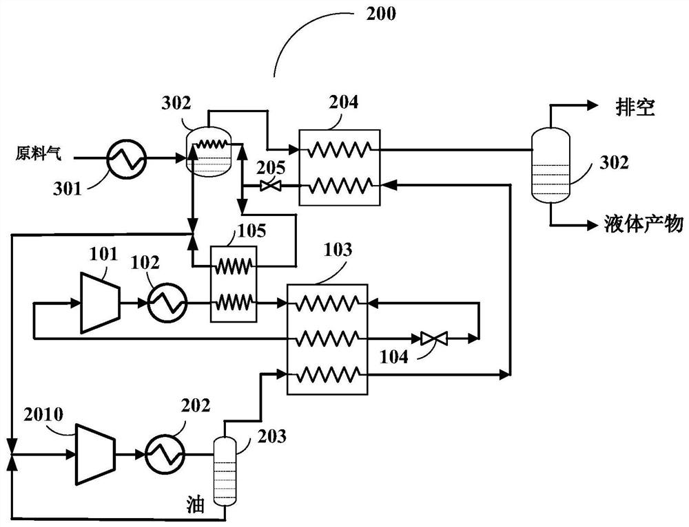
[0036] see image 3 , is a schematic structural diagram of a load-cooling cycle system provided by Embodiment 2 of the present invention. For the convenience of description, only the parts related to the embodiment of the present invention are shown, and the details are as follows.

[0037] A cooling cycle system 200 provided by the present invention includes: a mixed working medium refrigeration cycle and a cooling cycle; the mixed working medium refrigeration circuit includes a mixed working medium compressor (101), a mixed working medium condenser (102 ), a recuperative heat exchanger (103), a mixed working medium throttle valve (104) and a mixed working medium precooling heat exchanger (105); Refrigerant condenser (202), precision oil separation system (203), heat recovery heat exchanger (103), distributed heat exchanger (204), brine throttle valve (205) and feed gas precooling separator (302);

[0038] The high-pressure refrigerant outlet of the mixed working medium com...


PUM


Abstract

The cooling cycle system provided by the present invention includes: a mixed working medium refrigeration cycle circuit and a cooling cycle circuit; the mixed working medium refrigeration circuit includes a mixed working medium compressor (101), a mixed working medium condenser (102), a return heat exchanger (103), mixed working medium throttle valve (104); the brine-cooled circulation loop includes brine-driven pump (201), brine condenser (202), precision oil separation system (203) , regenerative heat exchanger (103), distributed heat exchanger (204) and feed gas pre-cooling separator (302), the cooling circulation system provided by the present invention utilizes the common or mixed working fluid with low freezing point The cold cycle is used as a load-cooling cycle, and it is driven by high-reliability general cooling temperature zone drive components, avoiding the use of low-reliability low-temperature circulation pumps, and can realize remote transmission of cold energy at -60°C or even liquid nitrogen temperature zones. The structure is simple and compact, and the cost is low. Inexpensive, high-efficiency operation; and non-flammable working fluid can be used in the load-cooling cycle, which has high safety in special occasions.

Description

technical field [0001] The invention relates to the technical field of load cooling, in particular to a load cooling cycle system. Background technique [0002] Mixed refrigerant refrigeration technology has been widely used in the liquefaction of natural gas since the 1970s, and has become the leading technology in the field of liquefied natural gas (LNG). However, there are limitations when cryogenic mixed refrigerant refrigeration technology is used in air liquefaction separation or oxygen liquefaction, etc., but the mixed refrigerant usually contains hydrocarbon flammable components. A spill, where hydrocarbons come into contact with Air Liquide (liquid oxygen), will react violently, posing serious safety concerns. Therefore, there are serious safety hazards in the direct application of the multi-component mixed refrigeration technology containing combustible components in low-temperature air liquefaction separation systems or oxygen liquefaction and other occasions. I...

Claims


Application Information

Patent Timeline
Patent Type & Authority Patents(China)
IPC IPC(8): F25B41/40F25B43/02F28D20/00
CPCF25B43/02F28D20/0034F25B41/40Y02E60/14
Inventor 公茂琼郭浩
Owner TECHNICAL INST OF PHYSICS & CHEMISTRY - CHINESE ACAD OF SCI
Why Eureka
Try Eureka