Rain pipe air-through-tunnel building external wall face cooling system and method

A rainwater pipe and tunnel air technology, applied in the sewer system, waterway system, ventilation system, etc., can solve problems such as difficult to meet temperature requirements, and achieve the effect of reducing system cost and cooling load

Pending Publication Date: 2019-12-10
ZHEJIANG SCI-TECH UNIV
View PDF9 Cites 1 Cited by
  • Summary
  • Abstract
  • Description
  • Claims
  • Application Information

AI Technical Summary

Problems solved by technology

This requires the tunnel to have a certain depth, otherwise it will be difficult to meet the temperature requirements.

Method used


Image

  • Rain pipe air-through-tunnel building external wall face cooling system and method
  • Rain pipe air-through-tunnel building external wall face cooling system and method
  • Rain pipe air-through-tunnel building external wall face cooling system and method

Examples


Embodiment 1

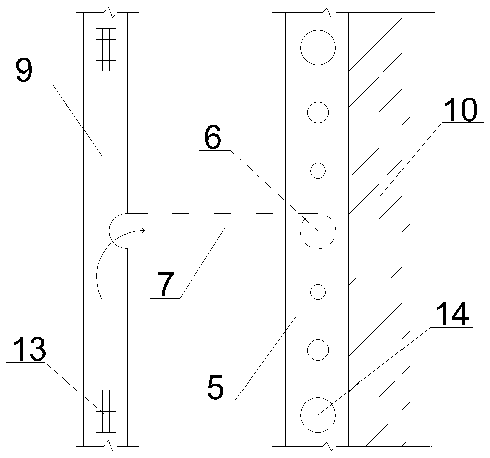
[0040] Embodiment 1, rainwater pipe tunnel wind building exterior wall surface cooling system, applied to buildings, such as Figure 1-2 as shown,

[0041] Utilize the rainwater pipeline buried in the outdoor ground 8 around the building as the underground air duct 7, form a rectangular heating cavity 4 with a metal partition on the outer surface of the building exterior wall 10, and the material used for the metal partition can be after anti-corrosion treatment steel plate, stainless steel plate, aluminum alloy plate, etc. The underground air duct 7 communicates with the heating cavity 4. The system uses the underground air duct 7 (rainwater pipe) as the outdoor air cooling tunnel, and utilizes the thermal pressure (solar chimney effect) generated by the heating cavity 4 under solar radiation to provide outdoor air. The power is used to introduce the outdoor air cooled by the underground air duct 7 into the heated cavity 4.

[0042] Both ends of the rainwater main pipe 9 co...


PUM


Abstract

The invention provides a rain pipe air-through-tunnel building external wall face cooling system which comprises a rain main pipe, an underground duct line and a heated cavity. The rain main pipe is communicated with a catch basin. One end of the underground duct line is communicated with the rain main pipe, and the other end of the underground duct line is communicated with the bottom of the heated cavity. The heated cavity is formed in the external surface of a building external wall. A wall duct communicated with the indoor space is arranged on the building external wall. A second valve isarranged in the wall duct. An exhaust hole is formed in the top of the heated cavity and provided with a first valve. The upper half portion of the heated cavity is communicated with the indoor spaceof a building through the wall duct. The invention further provides a rain pipe air-through-tunnel building external wall face cooling method. The underground rain pipe is used as the air-through-tunnel pipe, so only the underground duct line needs to be added, the length of the underground duct line is equal to the distance between the external wall and an outdoor rain pipe, and rain can be discharged; and meanwhile, an outdoor gutter inlet is used as the outdoor air inlet, so the system cost is greatly reduced.

Description

technical field [0001] The invention relates to a cooling system for the outer wall surface of a rainwater pipe tunnel wind, in particular to a cooling system and method for the outer wall surface of a rainwater pipe tunnel wind building. Background technique [0002] Building energy consumption accounts for about a quarter of the total energy consumption of the society. Among the building energy consumption, the energy consumption of air conditioning accounts for the bulk. Vigorously promoting the Architecture Festival has become a national plan. Building energy saving can be divided into energy saving of building body and energy saving of building equipment system, among which energy saving of building body is particularly critical. The energy saving of the building body is mainly to do a good job of thermal insulation of the envelope structure and adopt passive methods to reduce building energy consumption. [0003] Summer heat When the solar radiation directly hits the...

Claims


Application Information

Patent Timeline
Patent Type & Authority Applications(China)
IPC IPC(8): F24F5/00F24F7/06F24S20/60E04B2/00E04F17/04E03F3/00
CPCF24F5/0046F24F7/06F24S20/60E04B2/00E04F17/04E03F3/00F24F2005/0064Y02B10/20Y02B10/40Y02E10/40
Inventor 姜坪林熙龙张元明魏晓雯
Owner ZHEJIANG SCI-TECH UNIV
Why Eureka
Try Eureka