Thermostatic valve and thermal management system comprising same

A temperature regulating valve and valve stem technology, applied in the direction of valve operation/release device, valve details, valve device, etc., can solve the problem of insufficient lubricating oil in the gearbox, insufficient lubricating oil in the thermal management system, and filling of the gearbox oil Complicated process and other issues, to achieve the effect of simple filling

Pending Publication Date: 2019-12-10
ZHEJIANG SANHUA AUTOMOTIVE COMPONENTS
View PDF11 Cites 0 Cited by
  • Summary
  • Abstract
  • Description
  • Claims
  • Application Information

AI Technical Summary

Problems solved by technology

When filling the thermal management system with lubricating oil, in order to allow part of the lubricating oil to be injected into the heat exchange device, it is necessary to fill in high-temperature lubricating oil so that part of the lubricating oil can be injected into the heat exchange device, so the current filling process of transmission oil is relatively complicated
If the temperature of the filled lubricating oil is not enough, the lubricating oil will not be injected into the heat exchange device, which will lead to insufficient lubricating oil in the thermal management system. For example, during normal use, a part of the lubricating oil will stay in the heat exchange device and In the connecting pipeline, the amount of lubricating oil in the gearbox will be insufficient

Method used


Image

  • Thermostatic valve and thermal management system comprising same
  • Thermostatic valve and thermal management system comprising same
  • Thermostatic valve and thermal management system comprising same

Examples


Embodiment Construction

[0018] The specific implementation manner of the present invention will be described below in conjunction with the accompanying drawings.

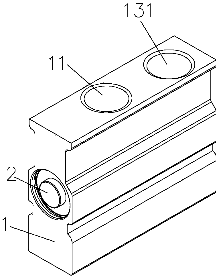
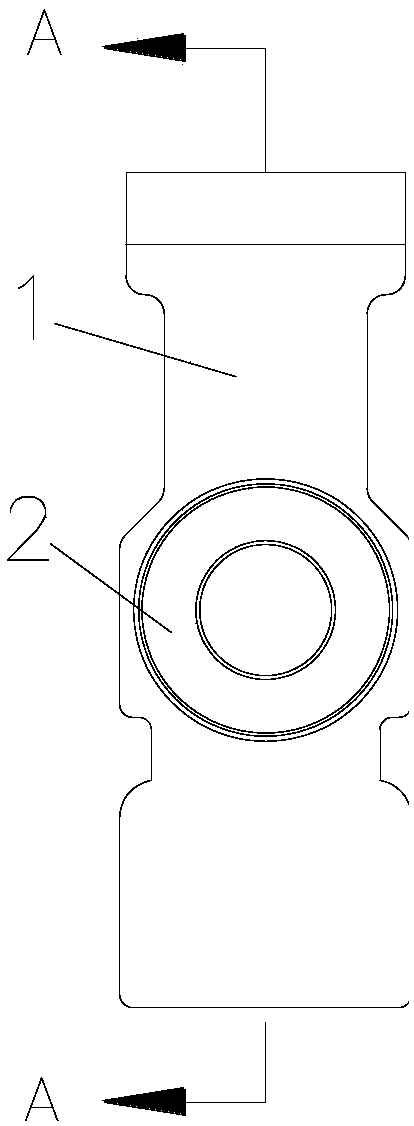
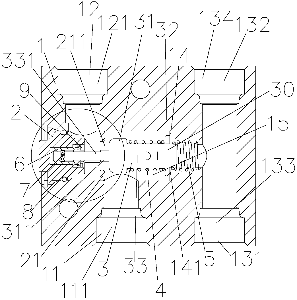
[0019] like Figures 1 to 3 As shown, the thermostatic valve includes a main valve body 1 , an end cover 2 , a thermal element 3 accommodated in the main valve body 1 , a second spring 4 and a first spring 5 . The main valve body 1 is provided with a first interface part 11, a second interface part 12, a third interface part 131 and a fourth interface part 132, wherein the first interface part 11 is provided with a first interface channel 111, and the second interface part 12 is provided with There is a second interface channel 121 , the third interface part 131 is provided with a third interface channel 133 , and the fourth interface part 132 is provided with a fourth interface channel 134 . The main valve body 1 is also provided with a valve body cavity 15 , and the end cover 2 is fixed to the main valve body 1 and the joint is sealed s...


PUM


Abstract

The invention discloses a thermostatic valve. The thermostatic valve has a first state and a first operating state. A hot melted material is arranged in an end cover of the thermostatic valve. in thefirst state, the hot melted material is in a solid state, and one end of a valve rod abuts against the hot melted material. Through arrangement of the hot melted material, a thermal dynamic element does not abut against a first valve seat, and a first valve port is opened. At the moment, the thermostatic valve is mounted in a thermal management system, the first valve port is opened, and in the lubricating oil charging process, lubricating oil can pass through a first interface channel, the first valve port and a second interface channel to flow into a heat exchange device. The thermal management system is simple in lubricating oil charging and also has the leakage detection function on the heat exchange device and a connecting pipe of the heat exchange device in the lubricating oil charging process.

Description

technical field [0001] The invention relates to the field of fluid control, in particular to a temperature regulating valve and a thermal management system with the temperature regulating valve. Background technique [0002] When the car is running, the parts need to be lubricated with lubricating oil in time to ensure the normal operation of the car, including transmission oil, which mainly realizes the temperature regulation function through the thermal management system. When the temperature of the transmission oil circuit rises, the heat-sensitive material of the thermodynamic element in the thermostat valve expands due to heat, and the channel through which the transmission oil in the thermostat valve directly flows back to the gearbox is blocked or the flow rate of the channel decreases. The high-temperature oil enters the heat exchange device through the temperature regulating valve to cool down and then flows back to the gearbox. Conversely, when the oil temperature...

Claims


Application Information

Patent Timeline
IPC IPC(8): F16H57/04F16K31/64
CPCF16H57/0435F16K31/002
Inventor 不公告发明人
Owner ZHEJIANG SANHUA AUTOMOTIVE COMPONENTS
Why Eureka
Try Eureka