Anti-deforming guide rail mounting structure of ultra-precision aspheric surface forming grinding machine

An installation structure and aspheric surface technology, which is applied in the field of anti-deformation guide rail installation structure of ultra-precision aspheric surface forming grinders, can solve problems such as uneven installation surface, easy protruding installation surface, guide rail deformation, etc., to eliminate key factors and avoid The effect of force

Pending Publication Date: 2019-12-10
中国机械总院集团海西(福建)分院有限公司
View PDF0 Cites 0 Cited by
  • Summary
  • Abstract
  • Description
  • Claims
  • Application Information

AI Technical Summary

Problems solved by technology

[0003] The traditional guide rail installation structure uses large-size screws, the screw spacing is large, the force is relatively uneven, and it is easy to cause deformation of the guide rail surface; the top port of the traditional threaded hole is chamfered or left untreated, and the thread on the top is easily protruded by the screw during installation. The installation surface will cause the installation surface to be uneven, which will easily cause the deformation of the guide rail

Method used


Image

  • Anti-deforming guide rail mounting structure of ultra-precision aspheric surface forming grinding machine
  • Anti-deforming guide rail mounting structure of ultra-precision aspheric surface forming grinding machine
  • Anti-deforming guide rail mounting structure of ultra-precision aspheric surface forming grinding machine

Examples


Embodiment Construction

[0022] The technical solutions in the embodiments of the invention will be clearly and completely described below in conjunction with the accompanying drawings in the embodiments of the invention. Obviously, the described embodiments are only part of the embodiments of the invention, not all of them. Based on the embodiments of the invention, all other embodiments obtained by persons of ordinary skill in the art without making creative efforts belong to the protection scope of the invention.

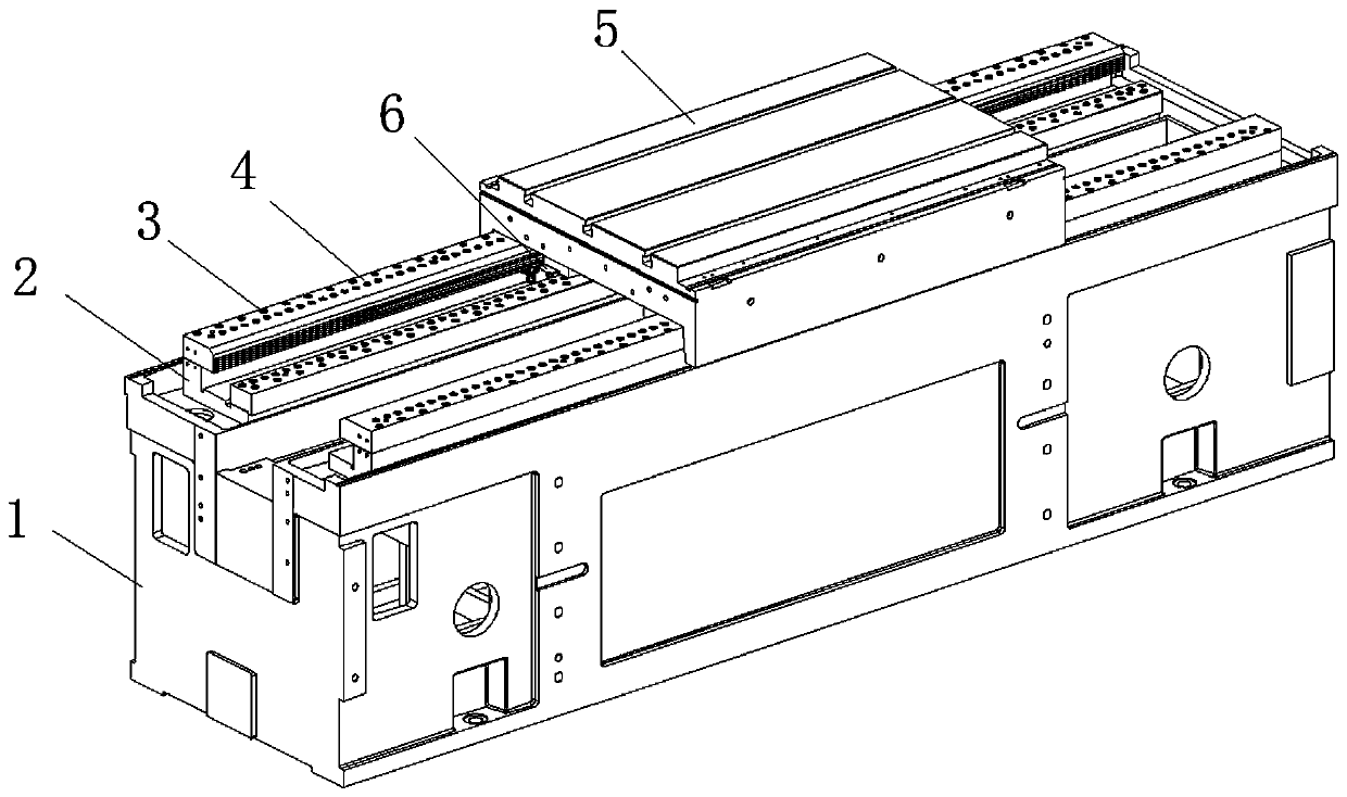
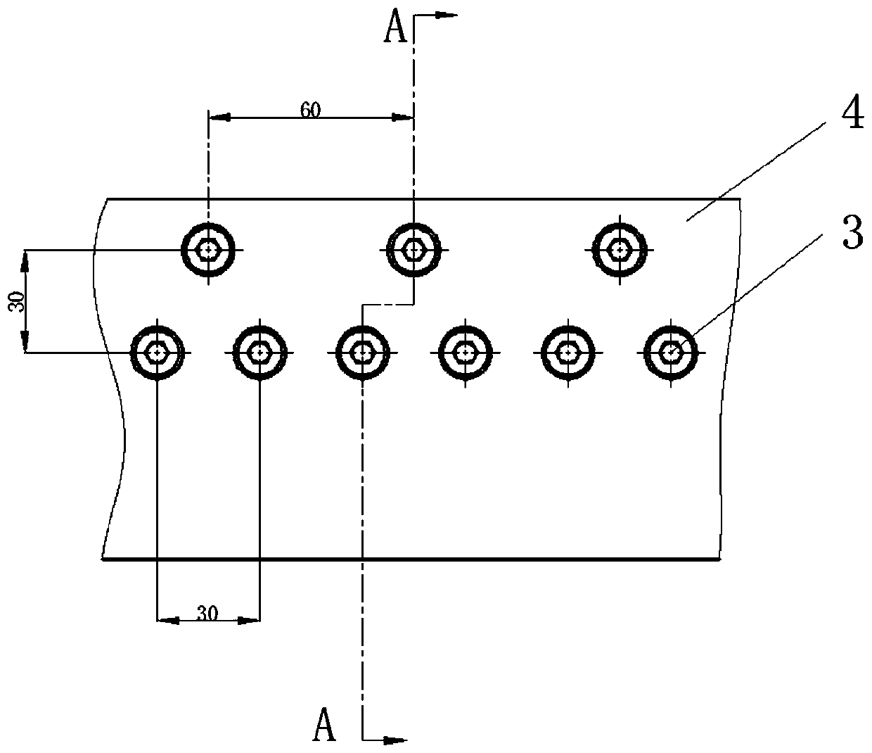
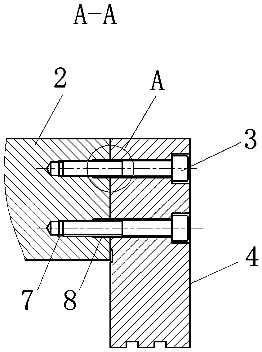
[0023] see Figure 1-4 , the invention provides a technical solution: an anti-deformation guide rail installation structure for an ultra-precision aspheric surface forming grinder, including a workbench base 1, and guide rail bases 2 are arranged on the front and rear sides of the top of the workbench base 1, and the guide rail The top of the base 2 is locked and fixed with a guide rail pressure plate 4 by a number of arrays of hexagon socket head cap screws 3 densely distributed. The to...


PUM

PropertyMeasurementUnit
Apertureaaaaaaaaaa
Depthaaaaaaaaaa

Abstract

The invention discloses an anti-deforming guide rail mounting structure of an ultra-precision aspheric surface forming grinding machine, and belongs to the technical field of anti-deforming guide railmounting structures. The anti-deforming guide rail mounting structure comprises a workbench base, and guide rail bases are arranged on the front side and the rear side of the top of the workbench base. A guide rail pressing plate is locked and fixed to the top of the guide rail base through a plurality of rows of socket head cap screws closely arranged in an array, and a workbench is arranged atthe top of the guide rail pressing plate. The workbench and the guide rail pressing plate achieve transverse sliding by arranging a static pressure sliding block, threaded holes matched with the socket head cap screws are formed in the top of the guide rail base, and anti-distortion counter bores are formed in upper end openings of the threaded holes. According to the anti-deforming guide rail mounting structure of the ultra-precision aspheric surface forming grinding machine, the key causing factor causing protruding deformation of the top face of the guide rail pressing plate can be eliminated, and then the function of preventing stress deformation is achieved.

Description

technical field [0001] The invention relates to the technical field of an anti-deformation guide rail installation structure, in particular to an anti-deformation guide rail installation structure for an ultra-precision aspheric surface forming grinder. Background technique [0002] Aspherical lenses are widely used in cameras, optical instruments, communications, astronomy and military industries. The processing method of aspheric lens is completed by first coarse grinding and then precision grinding and precision polishing with special equipment. For grinding machines, the guide rail used to install the workbench is one of the important structures that affect the final machining accuracy of the product. [0003] The traditional guide rail installation structure uses large-size screws, the screw spacing is large, the force is relatively uneven, and it is easy to cause deformation of the guide rail surface; the top port of the traditional threaded hole is chamfered or left ...

Claims


Application Information

Patent Timeline
IPC IPC(8): B24B13/00B24B41/02
CPCB24B13/00B24B41/02
Inventor 刘文志姜超黄清滨林鸿榕
Owner 中国机械总院集团海西(福建)分院有限公司
Why Eureka
Try Eureka