Quick power-down signal detection circuit and power-on reset device for detecting power supply voltage jitter

A technology for detecting circuit and power supply voltage, which is applied in the direction of measuring devices, measuring current/voltage, power supply testing, etc., can solve problems such as failure to meet design requirements, failure to generate reset signals, etc., to achieve fast power-off and slow power-off, The effect of improving detection response speed

Active Publication Date: 2019-12-06
NANKAI UNIV +1
View PDF7 Cites 5 Cited by
  • Summary
  • Abstract
  • Description
  • Claims
  • Application Information

AI Technical Summary

Problems solved by technology

[0004] The best current technology can achieve the fastest detection speed of the power supply voltage jitter is 1ms. When the power supply voltage jitter speed is faster than 1ms, the reset signal cannot be generated, which cannot meet the design requirements.

Method used


Image

  • Quick power-down signal detection circuit and power-on reset device for detecting power supply voltage jitter
  • Quick power-down signal detection circuit and power-on reset device for detecting power supply voltage jitter
  • Quick power-down signal detection circuit and power-on reset device for detecting power supply voltage jitter

Examples


Embodiment 1

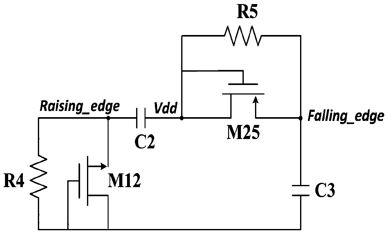
[0033] A fast power-down signal detection circuit of the present invention is an edge generation circuit that senses power supply voltage jitter and generates a spike signal, and is used to receive the spike signal and output a fast power-down signal generation circuit that outputs a fast power-down signal. The edge generation circuit includes MOS transistor M25 and MOS transistor M12, the gate and drain of the MOS transistor M25 are connected and connected through the resistor R 5 After connecting to its source, the gate and source of the MOS transistor M12 are connected through the resistor R 4 Then connected to its source, the gate of the MOS tube M25 is connected to the power supply voltage and passed through the capacitor C 2 Connected to the source of the MOS transistor M12, the source of the MOS transistor M25 passes through the capacitor C 3 Connected to the gate of the MOS transistor M12, the source of the MOS transistor M25 is the output point of the falling edge si...

Embodiment 2

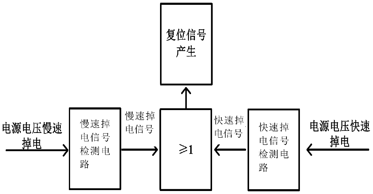
[0041] A power-on reset device for detecting power supply voltage jitter of the present invention includes:

[0042] The slow power-down signal detection module includes a switch unit that is turned on or off according to the change of the power supply voltage to generate a slow power-down signal,

[0043] The above-mentioned rapid power-down signal detection circuit, and the reset signal output module include a resistor-capacitor unit that is controlled by the switch unit or a quick-power-down signal to realize charging and discharging, and a resistor-capacitor unit that is connected to the resistor-capacitor unit to realize reset signal output. Reset signal generation unit.

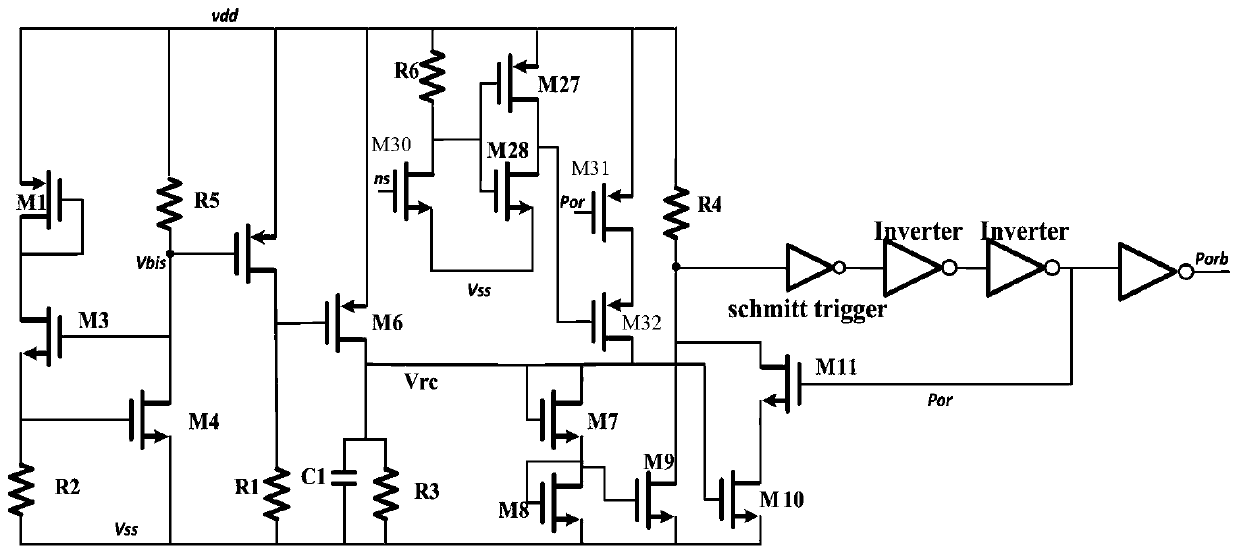
[0044] Further, for the slow power-down signal detection module, the switch unit includes a field effect transistor and a bias circuit, specifically, the switch unit includes a MOS transistor M5 and a MOS transistor M6, and the MOS transistor M5 and The sources of the MOS transistor M6 are respectively...


PUM


Abstract

The invention provides a quick power-down signal detection circuit and a power-on reset device for detecting power supply voltage jitter. The quick power-down signal detection circuit includes: an edge generating circuit which is used for sensing voltage jitter of a power supply and generating a peak signal; a quick power-down signal generation circuit which is used for receiving the peak signal and outputting a quick power-down signal, wherein the quick power-down signal generation circuit comprises a latch, wherein an output point of the falling edge signal is connected to an Ns point of a grid electrode of a first-stage phase inverter of the latch through a capacitor C6, an output point of the rising edge signal is connected to an s point output by the first-stage phase inverter of thelatch through a capacitor C5, and the Ns point outputs the fast power-down signal. Through power supply voltage jitter detection, an effective long-time reset signal is generated, and 10ns-level powerfailure detection can be realized at the soonest.

Description

technical field [0001] The invention relates to the technical fields of large-scale integrated circuits and power supply management, in particular to a fast power-down signal detection circuit and a power-on reset device for detecting power supply voltage jitter. Background technique [0002] When powering an electronic system, it takes time for the supply voltage to stabilize. In this transient period when the power supply voltage is stable, if the system is not reset by the trigger of the reset signal, for example, the initial state of the digital register and the analog integrator cannot be defined, that is, the circuit is in an unknown state, so the behavior of the entire circuit cannot be defined. Sure. Therefore, these circuits need a certain command signal to initialize the circuit during or after power-on, and this command signal is power-on reset (POR). The POR signal is supposed to hold the circuit in reset until the power supply reaches a steady state level wher...

Claims


Application Information

Patent Timeline
Patent Type & Authority Applications(China)
IPC IPC(8): H03K17/22H03K17/16G01R19/165G01R31/40
CPCG01R19/16538G01R31/40H03K17/161H03K17/223
Inventor 肖知明胡伟波房哲马伟
Owner NANKAI UNIV
Why Eureka
Try Eureka