Linkage switch device, power converter, power line and equipment
A technology of power converter and linkage switch, which is applied to the power device and contact drive mechanism inside the switch to achieve the effect of small size and avoiding standby power consumption
- Summary
- Abstract
- Description
- Claims
- Application Information
AI Technical Summary
Problems solved by technology
Method used
Image


Examples
Embodiment 1
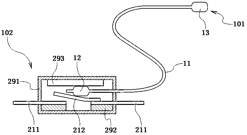
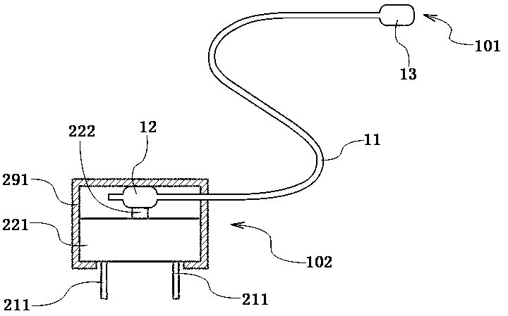
[0044] figure 1 A linkage switch device is shown, the linkage switch device is divided into a driving end 101 and a passive end 102, including a hydraulic device and a switch. The hydraulic device includes a connecting pipe 11 , a linkage bag 12 and a driving bag 13 . Two ends of the connecting tube 11 are respectively connected to the linkage capsule 12 and the driving capsule 13 , so that the linkage capsule 12 and the driving capsule 13 communicate through the connecting tube 11 . The connecting pipe 11, the interlocking bag 12 and the driving bag 13 are filled with liquid. The liquid filled in the connecting pipe 11, the interlocking bag 12 and the driving bag 13 can be water, or oil, or other liquids or mixed liquids. In order to avoid the problem that the temperature is too low in winter, the liquid condenses into a solid state, and the linkage switch device fails, in this embodiment, the liquid is preferably antifreeze. The freezing point of the antifreeze is -40°C. ...
Embodiment 2
[0054] Figure 4 A power converter to which the interlock switching device of Embodiment 1 is applied is shown. The power converter includes a power conversion unit 591 , a first connector 51 , a second connector 52 and a linkage switch device. The power conversion unit 591 and the linkage switch device are disposed in the converter housing 592 ; the first connector 51 and the second connector 52 are disposed on the converter housing 592 . The linkage switch device is image 3 The linkage switch device in the above will not be described in detail. The power converter is commonly referred to as a charger, wherein the first connector 51 is a power plug; the second connector 52 is usually a common USB interface. The power conversion unit 591 is used for power conversion. Its input part is connected to the first connector 51 through the switch of the linkage switch device, and its output part is connected to the second connector 52 for converting the voltage and current input t...
Embodiment 3
[0066] The linked switching device in Embodiment 1 is applied to the power converter in Embodiment 2, which can avoid the power converter standby problem. Specifically, for example, as a mobile phone charger as a power converter, the joint connected to the mobile phone is the second connector of the power converter. When the joint of the mobile phone charger as the second connector is docked with the mobile phone to charge the mobile phone, the power plug and its power conversion unit connected to the mobile phone charger through the linkage switch device in the second connector; When the connector of the mobile phone is unplugged from the mobile phone, the power plug of the mobile phone charger is disconnected from its power conversion unit, thereby avoiding standby power consumption when the mobile phone charger is not connected to the mobile phone. Those skilled in the art understand that the above linkage switch device itself can also be used as an independent switch, such...
PUM
 Abstract
Description
Claims
Application Information
 - R&D
- Intellectual Property
- Life Sciences
- Materials
- Tech Scout
- Unparalleled Data Quality
- Higher Quality Content
- 60% Fewer Hallucinations
Browse by: Latest US Patents, China's latest patents, Technical Efficacy Thesaurus, Application Domain, Technology Topic, Popular Technical Reports.
© 2025 PatSnap. All rights reserved.Legal|Privacy policy|Modern Slavery Act Transparency Statement|Sitemap|About US| Contact US: help@patsnap.com