
Acousto-optic electronic map system

An electronic map, acousto-optic technology, applied in the field of acousto-optic electronic map system, can solve the problem of dense defense area, unable to quickly identify and determine the specific location of the defense area, LED lights unable to clearly see the alarm defense area and location, unable to quickly convey the alarm situation and other problems

Pending Publication Date: 2019-12-06
上海亘想科技有限公司
View PDF0 Cites 0 Cited by
  • Summary
  • Abstract
  • Description
  • Claims
  • Application Information

AI Technical Summary

Problems solved by technology

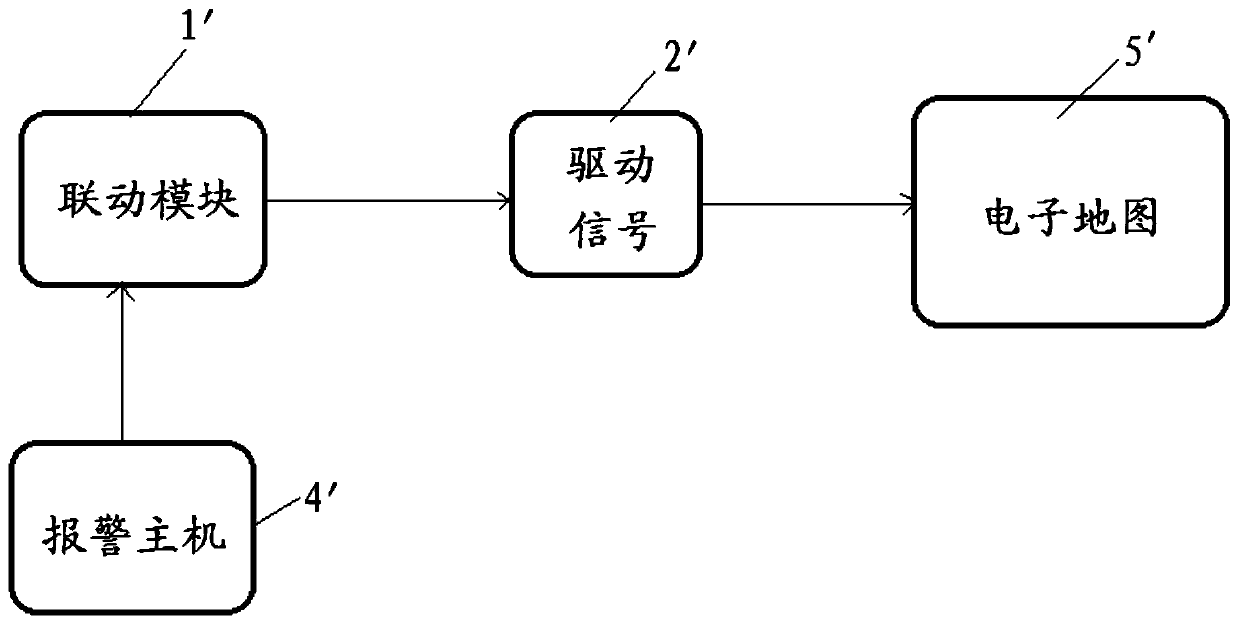
[0005] (1) Due to the dense defense area, it is impossible to quickly identify and determine the specific location of the defense area. In the traditional alarm system, a defense area alarm corresponds to an LED light in the analog electronic map to indicate;
[0006] (2) The electronic map of the prior art has only LED lights and no sound, and it is impossible to determine what kind of alarm it is. The technical means of the alarm has visual disadvantages in some security projects with dense defense areas and a large number of defense areas, such as prison detention centers and treasuries. The alarm defense areas such as the arsenal and the arsenal are densely packed, and security personnel cannot quickly identify the location of the defense area with the naked eye, and cannot quickly convey the specific location of the alarm situation.
In addition, the non-standard electronic analog alarm map equipped in the current security alarm, using the more dazzling LED lights, it is even impossible to see the alarm zone and location clearly;
[0007] (3) The existing technology cannot judge the system state, the state of arming and disarming, whether the alarm system is running normally, etc.

Method used


Image

  • Acousto-optic electronic map system
  • Acousto-optic electronic map system
  • Acousto-optic electronic map system

Examples


Embodiment Construction

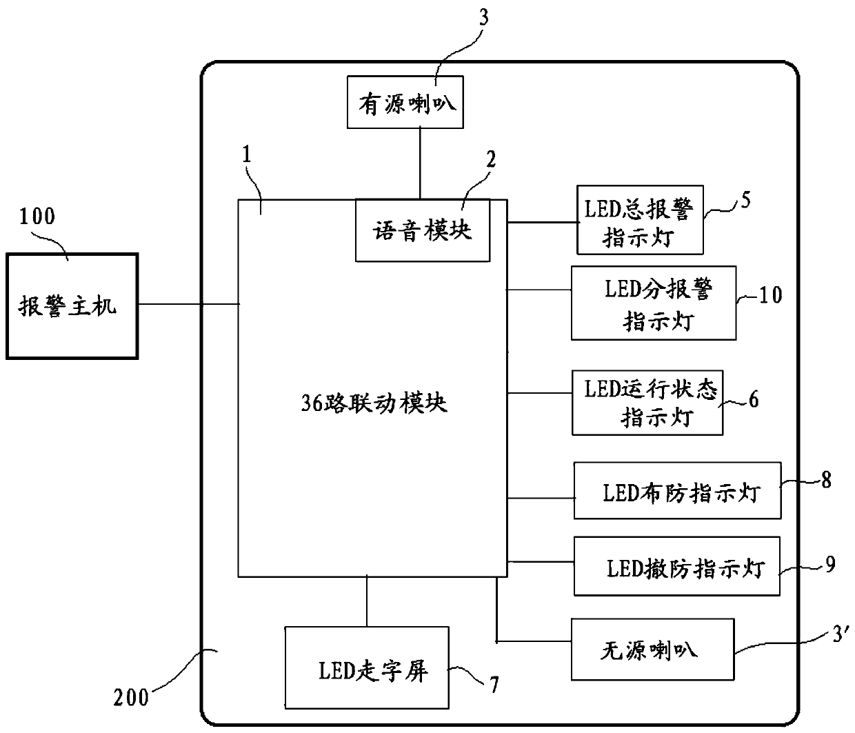
[0022] In order to enable those skilled in the art to better understand the technical solution of the present invention, its specific implementation will be described in detail below in conjunction with the accompanying drawings:

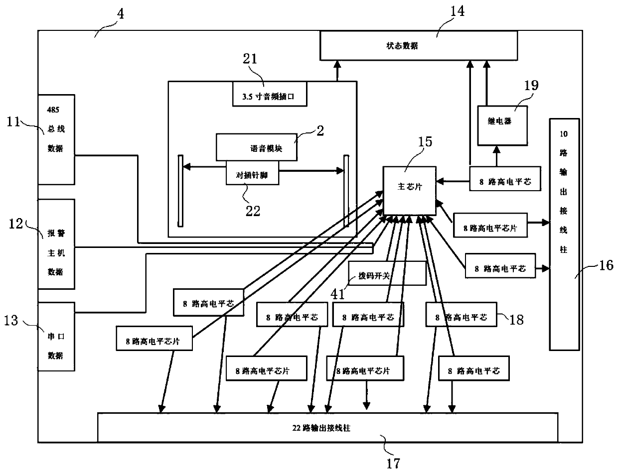
[0023] see figure 2 and image 3 , the best embodiment of the present invention, an acousto-optic electronic map system, including a 36-way linkage module 1, a voice module 2, a passive speaker 3', an active speaker 3, an inkjet plastic printing plate 200, and a total LED alarm indicator light 5 , LED running status indicator light 6, LED walking character screen 7, LED arming indicator light 8, LED disarming indicator light 9 and several LED subalarm indicator lights 10.

[0024] The 36-way linkage module 1 includes a main chip 15, 32-way output terminals 16 / 17, 485 bus data interface 11, alarm host data interface 12, serial port data interface 13, and status data interface 14. The 36-way linkage module 1 is set on a spray-painted plastic On the...


PUM


Abstract

The invention discloses an acousto-optic electronic map system. The acousto-optic electronic map system comprises 36-channel linkage module, a voice module, a passive loudspeaker, an active loudspeaker, an inkjet plastic printing board, an LED general alarm indicator lamp, an LED operation state indicator lamp, an LED word display screen, an LED arming indicator lamp, LED disarming indicator lampand several LED sub-alarm indicator lamps, the 36-channel linkage module comprises a main chip, a 32-channel output binding post, a 485 bus data interface, an alarm host data interface, a serial portdata interface and a state data interface, and the voice module is connected with the main chip of the 36-channel linkage module; and the 485 bus data interface, the alarm host data interface and theserial port data interface are respectively connected with an alarm host. The acousto-optic electronic map system disclosed by the invention has both light and sound, can directly indicate the type ofdanger, does not need to rely on computer control, detaches from the software, realizes simultaneous alarm and voice playing, is formed in one piece and is free from subsequent maintenance, so that the alarm technology is more human friendly.

Description

technical field [0001] The invention relates to an acousto-optic electronic map system. Background technique [0002] The use of security analog electronic maps in anti-theft alarm systems is relatively common. Most of the electronic maps use the way of marking the building CAD plane pictures to display the system, which is a relatively traditional application mode. Most of them use LED lights to light up at the position of the alarm zone to display the alarm situation. It belongs to a more traditional application mode. In actual use, it has the advantages of simple operation and intuitive response to the alarm situation. It is used as a perimeter alarm by various local technical defense departments. Indispensable standard configuration equipment in the system. [0003] see figure 1 , the prior art linkage function only links the LED lights on the security simulation electronic map 5', and can only check the location of the lights at a close distance. If the number of defe...

Claims


Application Information

Patent Timeline
Patent Type & Authority Applications(China)
IPC IPC(8): G08B7/06H05B33/08H05B44/00
CPCG08B7/06Y02B20/30
Inventor 黄一鸣
Owner 上海亘想科技有限公司
Learn More