
Low-frequency project ultra-strong capacitive coupling structure

A capacitive coupling and project technology, applied in the filter field, can solve problems such as shortening design time, difficult process control, tightening assembly tolerances, etc., to achieve the effect of being suitable for mass production, enhancing coupling, and reducing power consumption

Pending Publication Date: 2019-12-03
苏州诺泰信通讯有限公司
View PDF0 Cites 1 Cited by
  • Summary
  • Abstract
  • Description
  • Claims
  • Application Information

AI Technical Summary

Problems solved by technology

[0002] In the capacitive coupling structure design of traditional filters, the dumbbell structure is often used to achieve the customer's out-of-band suppression and other indicators, but when the frequency is relatively low and the out-of-band suppression is relatively strict, the dumbbell structure cannot meet the index requirements due to the height limit Sometimes the structure of the dumbbell will be increased to reduce the distance from the side wall of the resonant column to meet the index requirements. This kind of structure will often make the dumbbell very large, and the processing cost and difficulty will increase, and it will also lead to the side wall of the resonant column. The wall distance is very close and the assembly tolerance is tightened, which makes it difficult to control the process, and because of the short distance, it is easy to cause insufficient power and ignition. This design is a super capacitor structure designed to meet customer specifications. The structure can not only Solving debugging problems can also save costs and increase product stability. It can also shorten design time and improve product competitiveness.

Method used

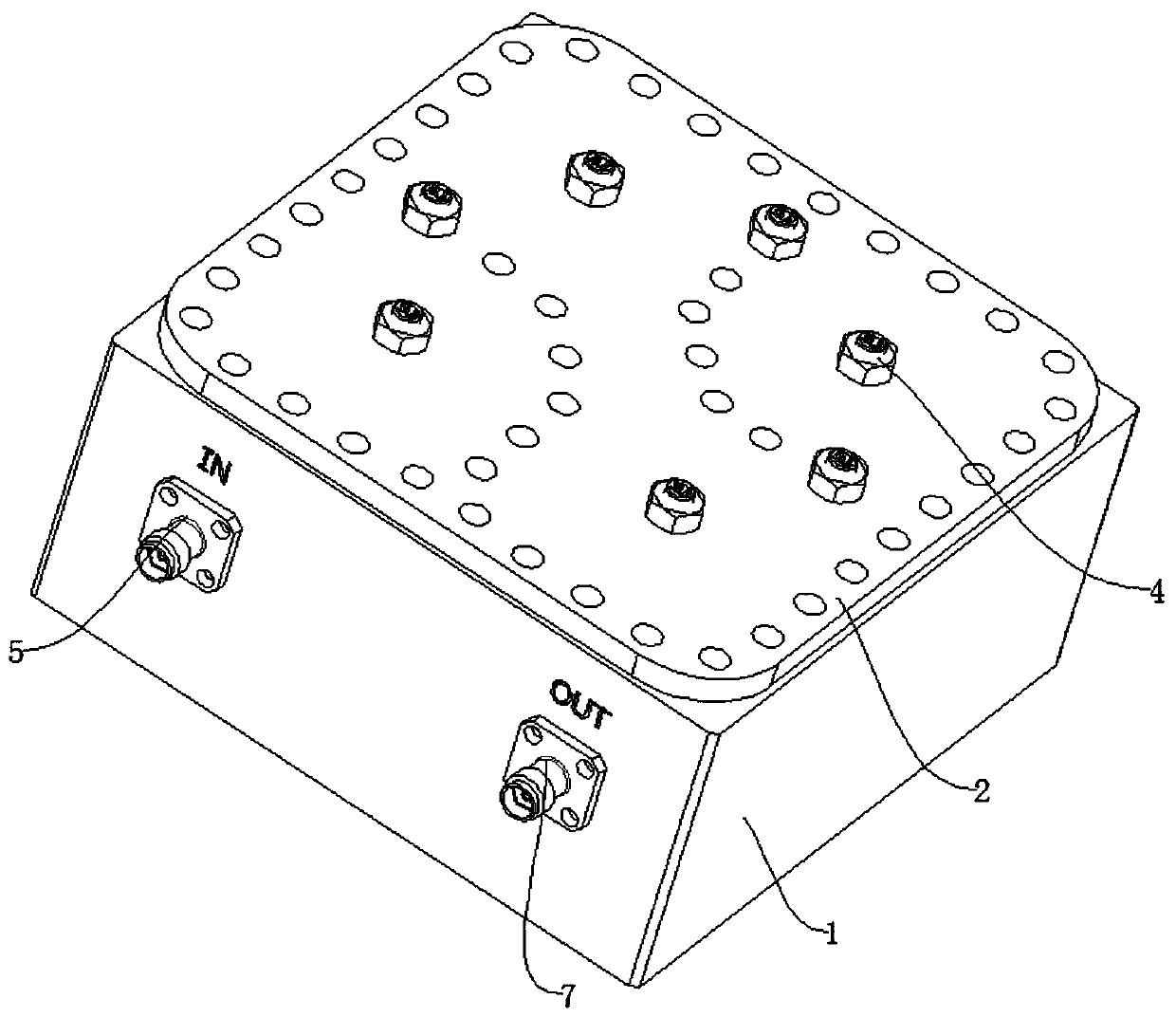
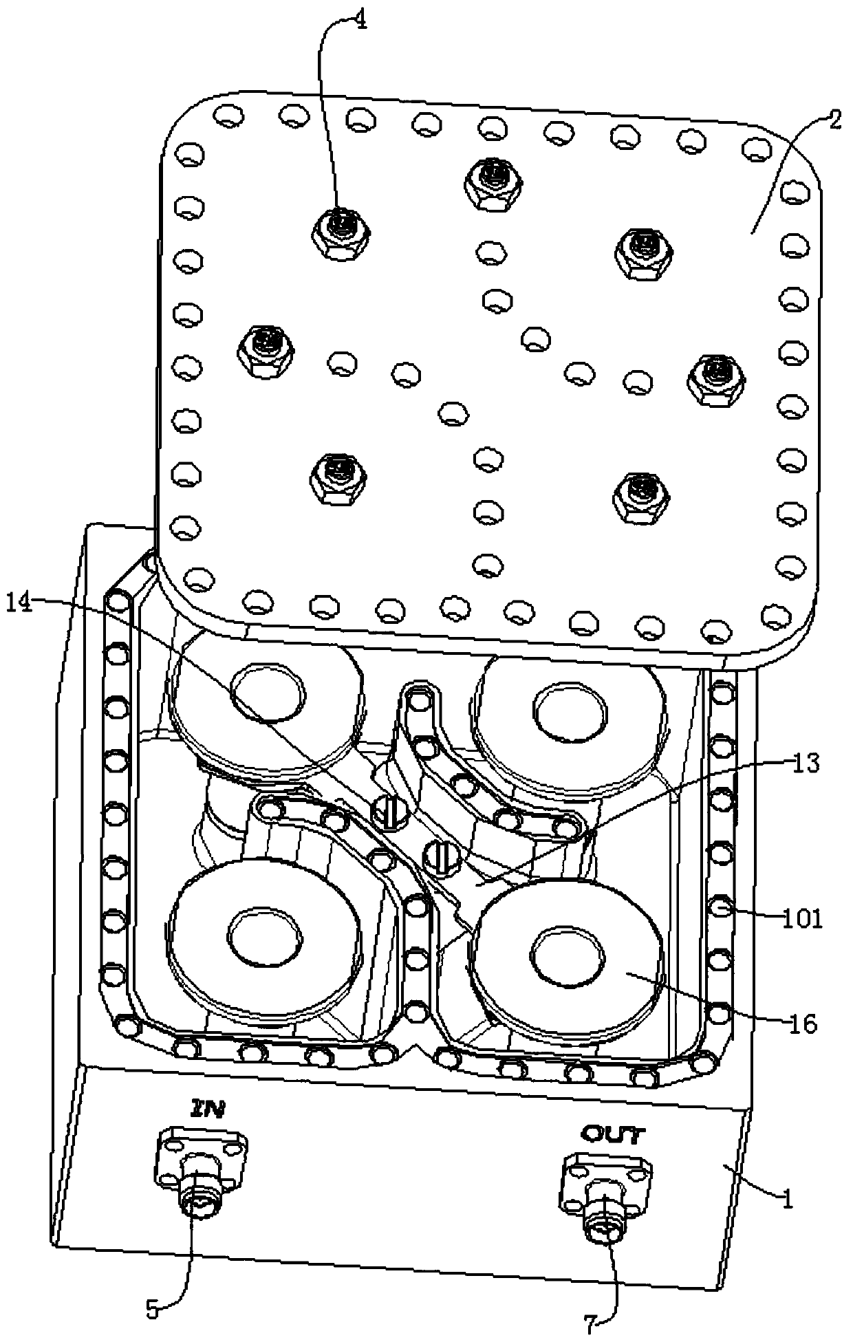
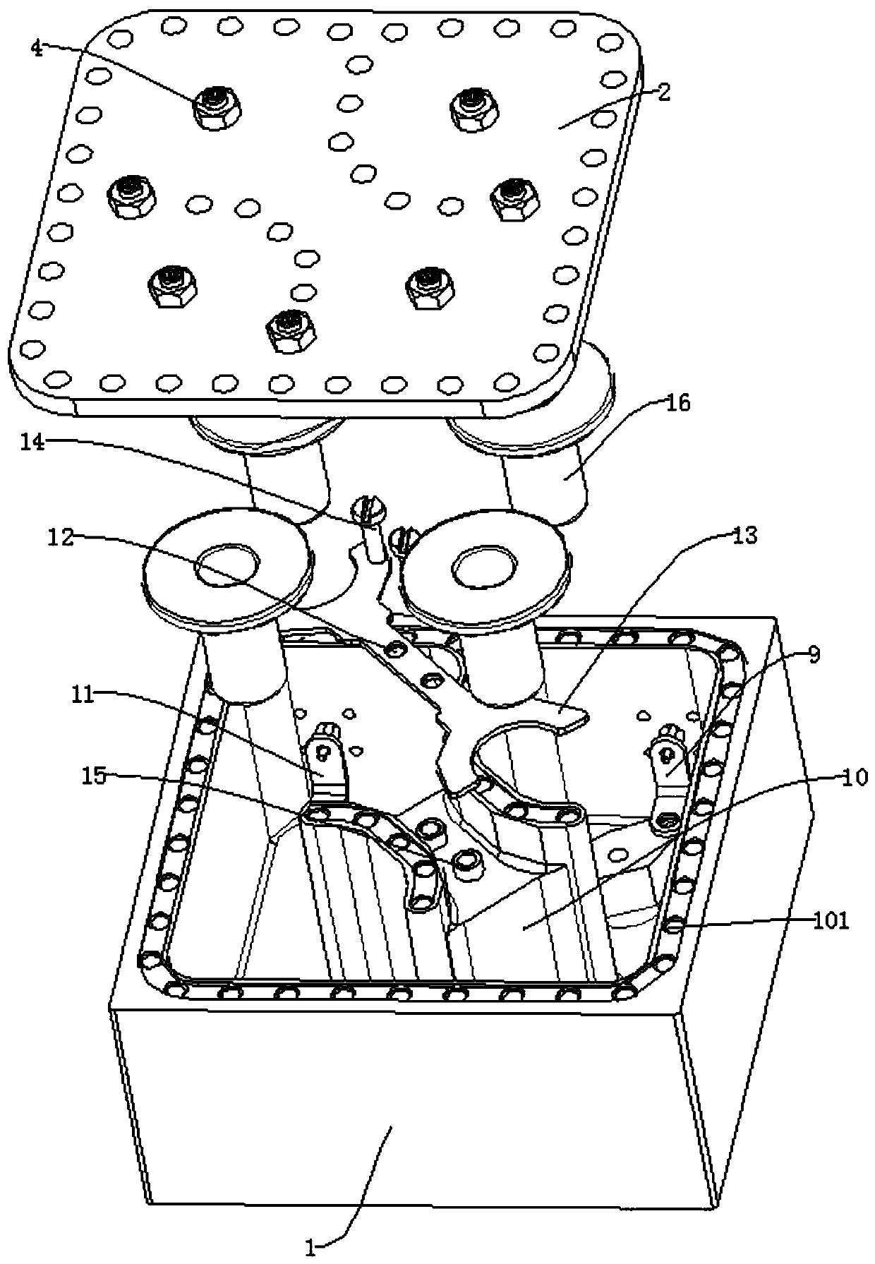

Image

  • Low-frequency project ultra-strong capacitive coupling structure
  • Low-frequency project ultra-strong capacitive coupling structure
  • Low-frequency project ultra-strong capacitive coupling structure

Examples


Embodiment Construction

[0020] The following will clearly and completely describe the technical solutions in the embodiments of the present invention with reference to the accompanying drawings in the embodiments of the present invention. Obviously, the described embodiments are only some, not all, embodiments of the present invention.

[0021] In describing the present invention, it should be understood that the terms "upper", "lower", "front", "rear", "left", "right", "top", "bottom", "inner", " The orientation or positional relationship indicated by "outside", etc. is based on the orientation or positional relationship shown in the drawings, and is only for the convenience of describing the present invention and simplifying the description, rather than indicating or implying that the referred device or element must have a specific orientation, so as to Specific orientation configurations and operations, therefore, are not to be construed as limitations on the invention.

[0022] refer to Figure ...


PUM


Abstract

The invention discloses a low-frequency project ultra-strong capacitive coupling structure, and belongs to the technical field of filters. The low-frequency project ultra-strong capacitive coupling structure comprises a filter body and resonators, the resonators are fixedly connected in the filter body, a mounting table is arranged in the filter body, the top of the mounting table is fixedly connected with a medium supporting piece, a connecting hole is formed in the medium supporting piece, the medium supporting piece is connected with a capacitive coupling copper sheet through a plastic screw, the capacitive coupling copper sheet is mainly composed of a connecting sheet and two arc-shaped clamping sheets, the two arc-shaped clamping sheets are connected to the two ends of the connectingsheet respectively, the connecting sheet and the two arc-shaped clamping sheets are integrally formed, the connecting sheet is provided with through holes corresponding to the plastic screws, and gapsare reserved between the two arc-shaped clamping sheets and the resonators. The low-frequency project ultra-strong capacitive coupling structure can be easily achieved, the stability and consistencyare easy to control, and the low-frequency project ultra-strong capacitive coupling structure is suitable for mass production.

Description

technical field [0001] The invention relates to the technical field of filters, in particular to a super-capacitive coupling structure for low-frequency items. Background technique [0002] In the capacitive coupling structure design of traditional filters, the dumbbell structure is often used to achieve the customer's out-of-band suppression and other indicators, but when the frequency is relatively low and the out-of-band suppression is relatively strict, the dumbbell structure cannot meet the index requirements due to the height limit Sometimes the structure of the dumbbell will be increased to reduce the distance from the side wall of the resonant column to meet the index requirements. This kind of structure will often make the dumbbell very large, and the processing cost and difficulty will increase, and it will also lead to the side wall of the resonant column. The wall distance is very close and the assembly tolerance is tightened, which makes it difficult to control ...

Claims


Application Information

Patent Timeline
Patent Type & Authority Applications(China)
IPC IPC(8): H01P1/207
CPCH01P1/207
Inventor 史作毅梁文超汪亭
Owner 苏州诺泰信通讯有限公司
Learn More