Dot projector structure and method for extracting image using dot projector structure

A projector and dot matrix technology, applied in the optical field, can solve the problems of increasing the production cost, reducing the accuracy of detecting and reconstructing virtual objects, etc., and achieving the effect of expanding the illumination angle

Inactive Publication Date: 2019-12-03
SRAY TECH IMAGE CO LTD
View PDF4 Cites 1 Cited by
  • Summary
  • Abstract
  • Description
  • Claims
  • Application Information

AI Technical Summary

Problems solved by technology

However, if elements such as diffuser mirrors are used to directly enlarge the irradiation angle of the dot matrix projector, since the total energy of irradiation is fixed, the energy and density of each light spot in each unit area will decrease accordingly, which will affect The infrared camera receives the reflected light point changes, thereby reducing the accuracy of detecting and reconstructing virtual objects
On the other hand, if a higher-precision diffractive optical element is used (for example, more light spots can be generated per unit area), the overall production cost will also increase

Method used


Image

  • Dot projector structure and method for extracting image using dot projector structure
  • Dot projector structure and method for extracting image using dot projector structure

Examples


Embodiment Construction

[0027] In order for those skilled in the art to have a better understanding of the present invention, preferred embodiments of the present invention are enumerated below, together with the accompanying drawings, to describe in detail the composition and desired effects of the present invention.

[0028] For the convenience of description, the drawings of the present invention are only schematic diagrams for easier understanding of the present invention, and the detailed proportions thereof can be adjusted according to design requirements. Those skilled in the art should be able to understand the relative positions of the relative elements in the drawings described in the text, so they can be turned over to present the same components, which should all belong to the disclosure of this specification. The scope is described here first.

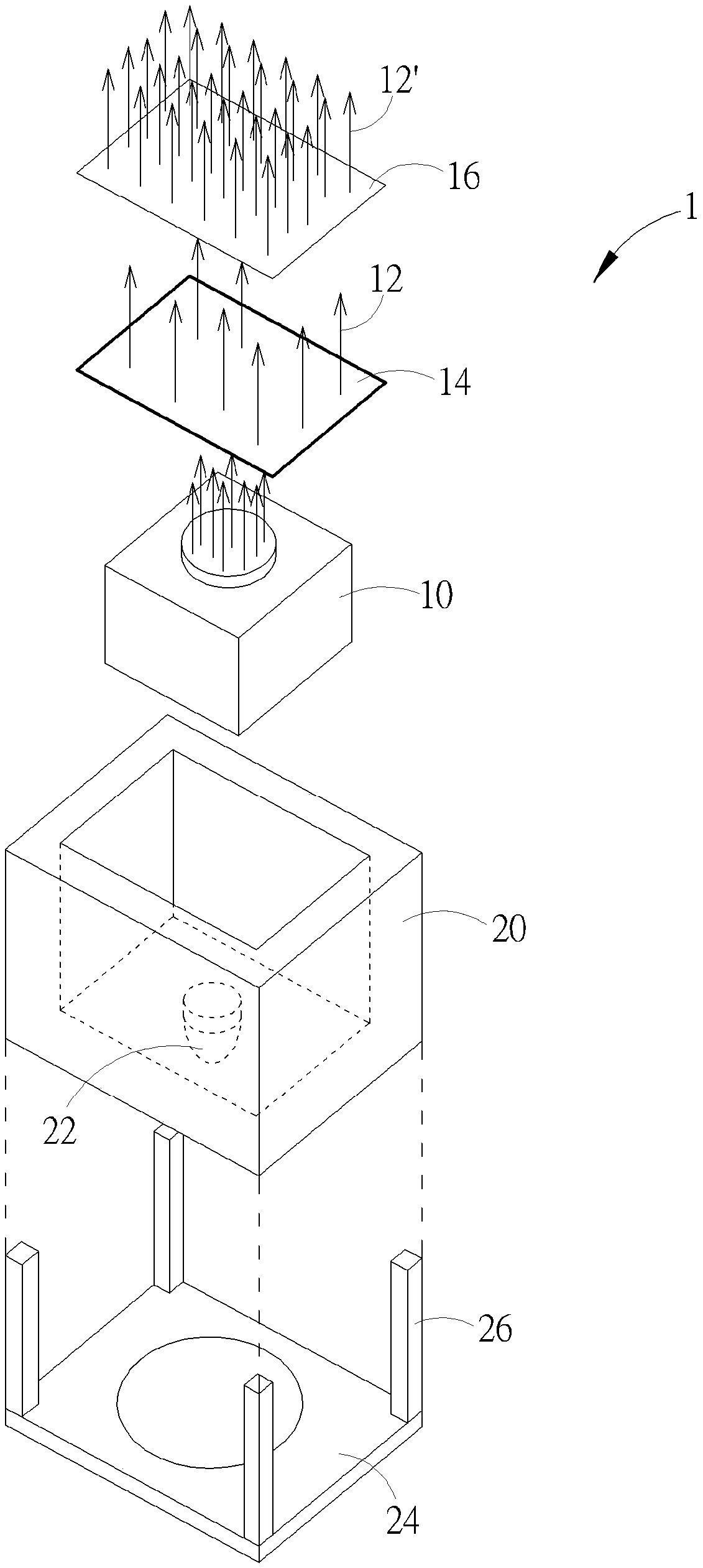
[0029] Please refer to figure 1 , which shows a schematic structural diagram of the dot matrix projector of the present invention. The dot mat...


PUM


Abstract

The present invention provides a dot projector structure and a method for extracting an image using the dot projector structure. The dot projector structure comprises a movable base, a light source emitter disposed above the movable base, a collimator, located in a front side of the light source emitter, a diffractive optical element (DOE) located in the front side of the light source emitter, andan actuator is connected to the movable base, the tilt angle of the movable base can be changed by providing a signal to the actuator. Via the above technical solution, an irradiation angle of the dot matrix projector can be expanded without reducing the detection precision and providing a high-precision diffractive optical element.

Description

technical field [0001] The present invention relates to the field of optics, in particular to a dot matrix projector structure capable of changing the irradiation angle, and a method for capturing images by the dot matrix projector structure. Background technique [0002] With the advancement of science and technology, mobile phones have become one of the indispensable belongings of modern people. Therefore, the protection technology of personal mobile phone data is constantly being researched and developed. [0003] In recent years, through the development of 3D stereoscopic image sensing technology, electronic products with face recognition function have gradually appeared on the market. Taking a mobile phone as an example, currently a mobile phone with a face recognition function at least includes devices such as a floodlight illuminator, a dot-matrix projector, and an infrared camera. The known face recognition process of a mobile phone generally includes three steps in...

Claims


Application Information

Patent Timeline
Patent Type & Authority Applications(China)
IPC IPC(8): G03B15/02G02B27/42
CPCG03B15/02G02B27/425H04N5/33G06V20/64G06V40/166G06V40/40H04N23/56F21V21/30
Inventor 郑训育
Owner SRAY TECH IMAGE CO LTD
Why Eureka
Try Eureka