
Novel sensing grid for displacement measurement and working method thereof

A technology for displacement measurement and direction measurement, which is applied in the direction of measuring devices, electric devices, and electromagnetic means, can solve the problems that glass carriers cannot achieve shock resistance and vibration characteristics, and achieve simple structure, extended application, and removal of interference signals and The effect of the noise signal

Inactive Publication Date: 2019-12-03
天津捷力自动化设备有限公司
View PDF8 Cites 0 Cited by
  • Summary
  • Abstract
  • Description
  • Claims
  • Application Information

AI Technical Summary

Problems solved by technology

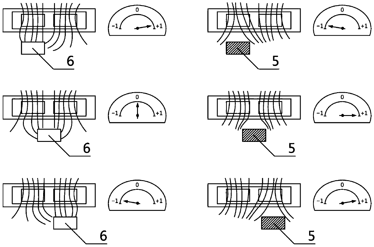
[0006] The purpose of the present invention is to provide a transformer-based inductance principle, through the structural redesign of the primary coil and the secondary coil, using the periodic changes brought about by the magnetic force lines generated by the coils, effectively overcoming the traditional grating anti-pollution Insufficient capacity, as well as the anti-shock and vibration characteristics that cannot be achieved by glass carriers, at the same time greatly reduce the high cost caused by lithography, and cooperate with the high-frequency excitation current in the circuit to improve the anti-interference ability of the signal and achieve precise displacement. A new sensor grid for measuring

Method used


Image

  • Novel sensing grid for displacement measurement and working method thereof
  • Novel sensing grid for displacement measurement and working method thereof
  • Novel sensing grid for displacement measurement and working method thereof

Examples


Embodiment Construction

[0029] The specific implementation manners of the present invention will be briefly described below in conjunction with the accompanying drawings.

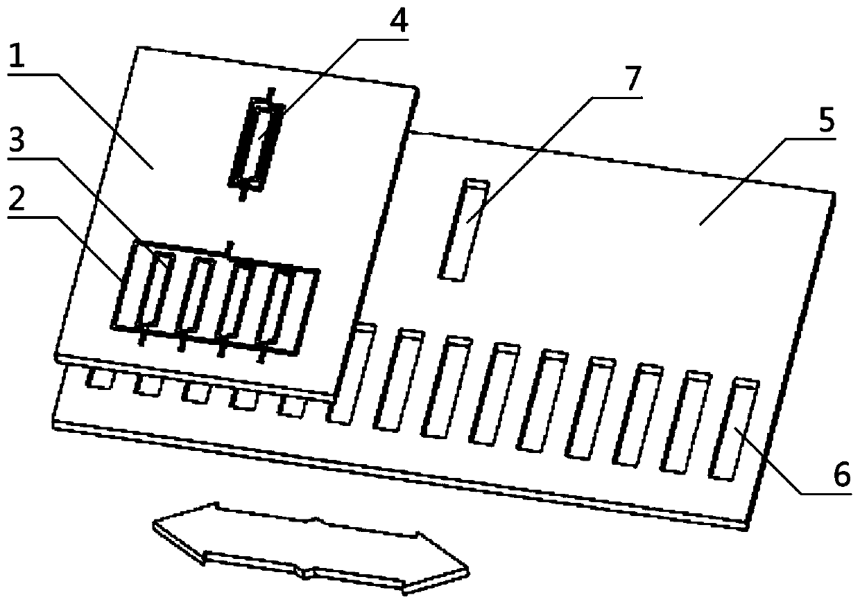
[0030] Such as figure 1 , figure 2 , image 3Shown is a new type of sensing grid for displacement measurement and its working method, which is characterized in that: it is composed of a measuring head structure 1 and a sensing grid ruler structure 5, and the measuring head structure 1 is located on the upper part of the sensing grid ruler structure 5, so The measuring head 1 is movably connected with the sensing grid ruler 5, and the measuring head structure 1 is also provided with a primary coil 2, four secondary coils 3 and a reference coil 4, and the primary coil 2 is located in the measuring head structure 1 Inside, the primary coil 2 is fixedly connected to the measuring head structure 1, the primary coil 2 is etched on the measuring head structure 1 by micro-multilayer technology, and the four secondary coils 3 are separa...


PUM


Abstract

The invention aims to provide a novel sensing grid for displacement measurement and a working method thereof. The technical scheme of the invention is that the novel sensing grid is formed by a measuring head structure and a sensing grating ruler structure, the measuring head structure can horizontally move on the sensing grating ruler structure, the measuring head structure is provided with a primary coil, four secondary coils and a reference coil, the four secondary coils are horizontally and uniformly distributed on an inner side of the primary coil at equal intervals, the sensing grating ruler structure is provided with a plurality of sensing gaps and a reference gap, a whole sensor is based on the inductance principle of a transformer, through the redesign of structures of the primarycoil and the secondary coils, precise displacement information and data can be obtained by using a periodic change caused by magnetic lines of force generated by the coils, the anti-interference capability and the signal quality of a signal are improved in cooperation with a high-frequency exciting current in the aspect of a circuit, the defects that a traditional optical grating has poor anti-pollution capability and the impact resistance and vibration resistance cannot be achieved are overcome, and the precise displacement measurement is realized.

Description

technical field [0001] The invention relates to the field of industrial precision measurement sensors, in particular to a novel sensing grid for displacement measurement and a working method thereof. Background technique [0002] With the development of numerical control technology, there is a high demand for precision displacement measurement in machining, electronics and precision measurement industries; displacement measurement sensors are similar to human eyes in the field of control, and can only be completed with accurate measurement of displacement Precise control, so as to achieve precise processing, improve product quality and the level of the entire industrial production and manufacturing industry. [0003] The current displacement measurement technologies mainly include laser interferometer and grating measurement technology; the measurement results of the laser interferometer are very accurate, and the measurement results can be directly traced to the length stan...

Claims


Application Information

Patent Timeline
Patent Type & Authority Applications(China)
IPC IPC(8): G01B7/02
CPCG01B7/001G01B7/02
Inventor 曹世智
Owner 天津捷力自动化设备有限公司
Learn More