
Shock absorption and noise reduction structure of automobile engine

A technology for automobile engine and noise reduction, applied in springs/shock absorbers, mechanical equipment, vibration suppression adjustment, etc., can solve the problems of hydraulic shock absorbers heating, weak shock absorbers, and the filtering effect is not as smooth as hydraulic shock absorbers. To achieve the effect of good driving and riding experience, good shock absorption effect and good filtering effect

Inactive Publication Date: 2019-12-03
QINGYUAN POLYTECHNIC
View PDF10 Cites 3 Cited by
  • Summary
  • Abstract
  • Description
  • Claims
  • Application Information

AI Technical Summary

Problems solved by technology

[0003] Nowadays, hydraulic shock absorbers and air shock absorbers are the most common in the automotive field, but both have advantages and disadvantages. Hydraulic shock absorbers are better at filtering large bumps, but when encountering small bumps, passengers in the car will feel Obvious road feeling, the air shock absorber handles fine bumps better, but when encountering larger bumps, the filtering effect is obviously not as smooth as the hydraulic shock absorber, and the hydraulic shock absorber will heat up when used for a long time This leads to a weak shock absorber, so a new type of shock absorber for automobiles that can fully filter both large and small bumps is required

Method used


Image

  • Shock absorption and noise reduction structure of automobile engine
  • Shock absorption and noise reduction structure of automobile engine
  • Shock absorption and noise reduction structure of automobile engine

Examples


Embodiment Construction

[0032] The following will clearly and completely describe the technical solutions in the embodiments of the present invention with reference to the accompanying drawings in the embodiments of the present invention. Obviously, the described embodiments are only some, not all, embodiments of the present invention.

[0033] In the description of the present invention, it should be noted that the terms "center", "upper", "lower", "left", "right", "vertical", "horizontal", "inner", "outer" etc. The indicated orientation or positional relationship is based on the orientation or positional relationship shown in the drawings, and is only for the convenience of describing the present invention and simplifying the description, rather than indicating or implying that the referred device or element must have a specific orientation, or in a specific orientation. construction and operation, and therefore cannot be construed as limiting the present invention; the terms "first", "second", and ...


PUM


Abstract

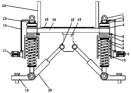
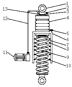
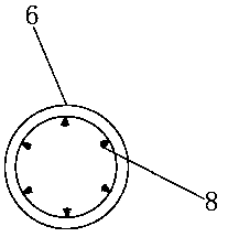
The invention discloses a shock absorption and noise reduction structure of an automobile engine. The shock absorption and noise reduction structure comprises a bag type air shock absorber and a hydraulic shock absorber, a bolt fixing hole is welded in the center of the top surface of the bag type air shock absorber, and one side of the bolt fixing hole penetrates through the top surface of the bag type air shock absorber and is provided with an air conveying hole; an air outlet pipe is arranged at the other side of the bolt fixing hole and penetrates through the top face of the bag type air shock absorber, an air outlet pipe electric switch is arranged on the top face of the air outlet pipe, and a hydraulic shock absorber is welded to the bottom face of the bag type air shock absorber; atemperature sensor is arranged on the surface of the hydraulic shock absorber, and a bolt fixing hole is welded to the bottom face of the hydraulic shock absorber. In the present invention, the bag type air shock absorber and the hydraulic shock absorber are arranged, the hydraulic shock absorber has a more obvious filtering effect for the larger jolts, the bag type air shock absorber has a more obvious filtering effect for the small jolts, with the combination of the hydraulic shock absorber and the bag type air shock absorber, the larger jolts can be fully filtered, meanwhile, the better filtering effect on the smaller jolts can be achieved, and the better driving and riding experience is brought to the automobile users.

Description

technical field [0001] The invention relates to the technical field of automobile shock absorbers, in particular to an automobile engine shock absorber and noise reduction structure. Background technique [0002] The shock absorber is used to suppress the shock when the spring rebounds after absorbing the shock and the impact from the road surface. It is widely used in automobiles to accelerate the attenuation of the vibration of the frame and the body to improve the ride comfort of the car. When passing through uneven roads, Although the shock-absorbing spring can filter the vibration of the road surface, the spring itself will reciprocate, and the shock absorber is used to suppress this kind of spring jumping. If the shock absorber is too soft, the body will jump up and down. It will bring too much resistance and prevent the spring from working normally. In the modification process of the suspension system, hard shock absorbers should be matched with hard springs, and the ...

Claims


Application Information

Patent Timeline
Patent Type & Authority Applications(China)
IPC IPC(8): F16F15/02F16F15/023F16F15/04
CPCF16F15/02F16F15/023F16F15/04
Inventor 胡列快孙乃谦
Owner QINGYUAN POLYTECHNIC
Learn More