Multi-stage ski-jump energy dissipation drainage system

A drainage system and energy dissipation technology, applied in the field of field engineering, to achieve the effect of collecting irrigation tail water, reducing soil loss, and good comprehensive performance

Inactive Publication Date: 2019-12-03
HOHAI UNIV
View PDF4 Cites 0 Cited by
  • Summary
  • Abstract
  • Description
  • Claims
  • Application Information

AI Technical Summary

Problems solved by technology

[0003] The technical problem to be solved in the present invention is to provide a multi-stage deflecting energy dissipation drainage system for the vacancy of existing field engineering

Method used


Image

  • Multi-stage ski-jump energy dissipation drainage system
  • Multi-stage ski-jump energy dissipation drainage system
  • Multi-stage ski-jump energy dissipation drainage system

Examples


Embodiment Construction

[0021] The following is a further description of the multi-stage deflected flow energy dissipation drainage system in conjunction with the accompanying drawings.

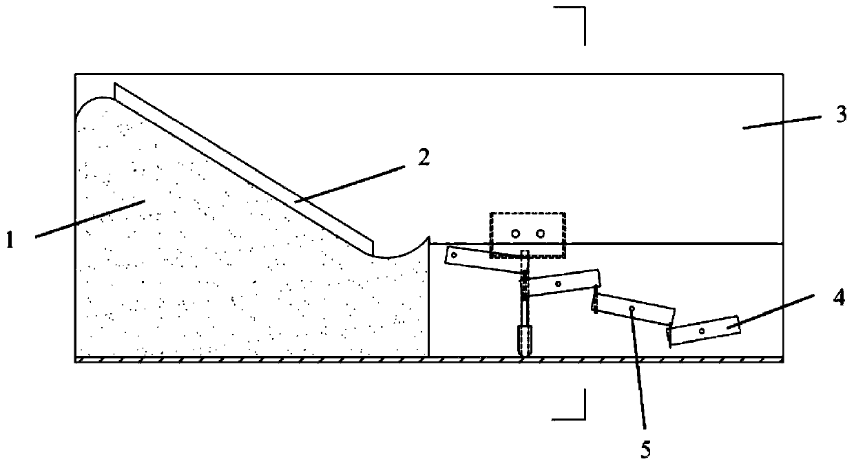
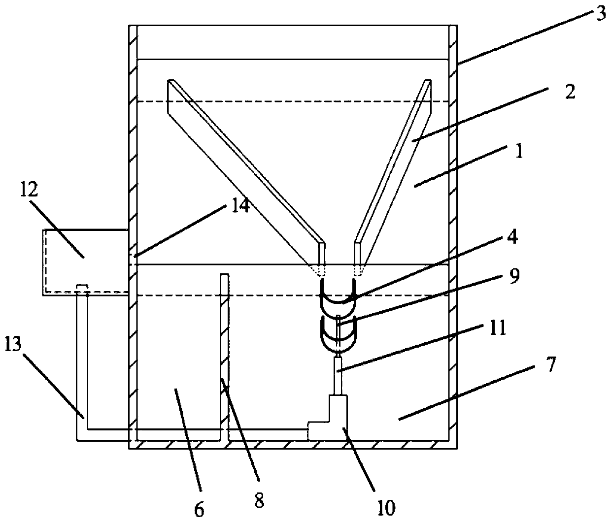
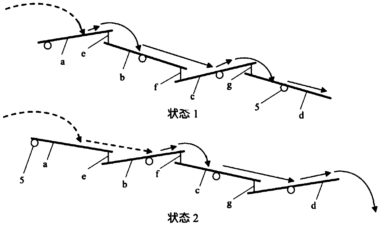
[0022] Such as Figures 1 to 3 , a multi-stage deflected flow energy dissipation drainage system, which generally includes three parts: an energy dissipation drainage channel, a field drainage system and a connecting device. Complete the collection of field tail water and discharge it into the field tail water discharge area in the energy dissipation drain, and the connection device supports the adjustment of the height of the connection shaft by the water pressure.

[0023] Such as Figure 1-3 As shown, the energy-dissipating drainage channel includes a deflector nose sill 1, a diversion wall 2, a water diversion channel wall 3, a diversion channel 4, a fixed shaft 5, a field tail water discharge area 6, an energy dissipation tail water discharge area 7, and partitions wall 8. The connecting device comprises a c...


PUM


Abstract

The invention discloses a multi-stage ski-jump energy dissipation drainage system. The multi-stage ski-jump energy dissipation drainage system comprises a flip bucket, partition walls and a pluralityof flow guide channels, wherein the flip bucket, the partition walls and the flow guide channels are sequentially arranged in the water outlet direction of a diversion channel; a V-shaped flow guide wall is arranged on the flip bucket; the flow guide wall gathers water flow in the diversion channel to the flip bucket; water is lifted up by the flip bucket and then impacts into the flow guide channels; each partition wall is arranged on one side of the corresponding flow guide channel; a field tail water discharge area is formed by one sides of the partition walls and the wall, on one side, ofthe diversion channel; and an energy dissipation tail water discharge area is formed on the other sides of the partition walls and the wall, on the other side, of the diversion channel. The multi-stage ski-jump energy dissipation drainage system is applied to the tail end of a river diversion irrigation project with a relatively high water flow rate of a diversion river, and particularly has effects of reducing soil loss, collecting irrigation tail water and preventing river sediment deposition on farmlands with serious soil erosion. According to the multi-stage ski-jump energy dissipation drainage system, the water energy is utilized, energy conservation and environmental protection are achieved, meanwhile, the problems of water and soil loss and ski-jump energy dissipation are solved, and the comprehensive performance is good.

Description

technical field [0001] The invention belongs to the technical field of field engineering, and in particular relates to a multi-stage deflected flow energy dissipation drainage system. Background technique [0002] Field drainage system has always been an important part of field engineering. The commonly used water diversion irrigation method directly builds intake gates and barrages in the river for water intake. However, when this method is applied to rivers with rapid flow velocity and high sediment content, it is easy to aggravate the problem of soil erosion. In addition, the excess water energy is not fully utilized. A certain amount of energy waste is caused, and the excessive water flow rate also has a negative impact on agricultural production. If the tail water at the end of the diversion canal is used to dissipate energy for rivers with high water flow velocity at the water intake, the flow velocity can be slowed down while saving energy, which is beneficial to agr...

Claims


Application Information

Patent Timeline
Patent Type & Authority Applications(China)
IPC IPC(8): E02B11/00
CPCE02B11/00
Inventor 田汇文
Owner HOHAI UNIV
Why Eureka
Try Eureka