
Drafting system and drafting system unit for a spinning machine

A drafting device and spinning machine technology, applied in spinning machines, drafting equipment, textiles and papermaking, etc., can solve problems such as large operating force, achieve reliable force transmission and operating force, and simple structure

Active Publication Date: 2019-12-03
SAURER SPINNING SOLUTIONS GMBH & CO KG
View PDF9 Cites 0 Cited by
  • Summary
  • Abstract
  • Description
  • Claims
  • Application Information

AI Technical Summary

Problems solved by technology

[0004] However, the known adjustment possibilities of the pressurized saddles have the disadvantage that in particular high operating forces are required in the case of simultaneous adjustment of many interrelated pressurized saddles, for example guiding and loading a common upper roller

Method used


Image

  • Drafting system and drafting system unit for a spinning machine
  • Drafting system and drafting system unit for a spinning machine
  • Drafting system and drafting system unit for a spinning machine

Examples


Embodiment Construction

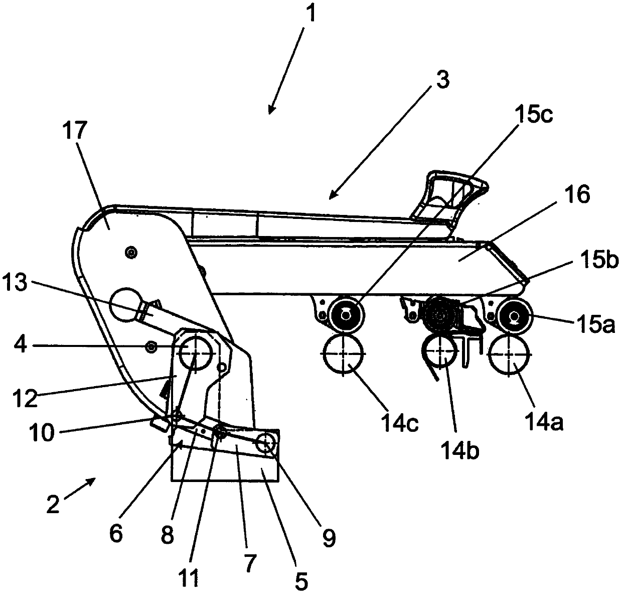
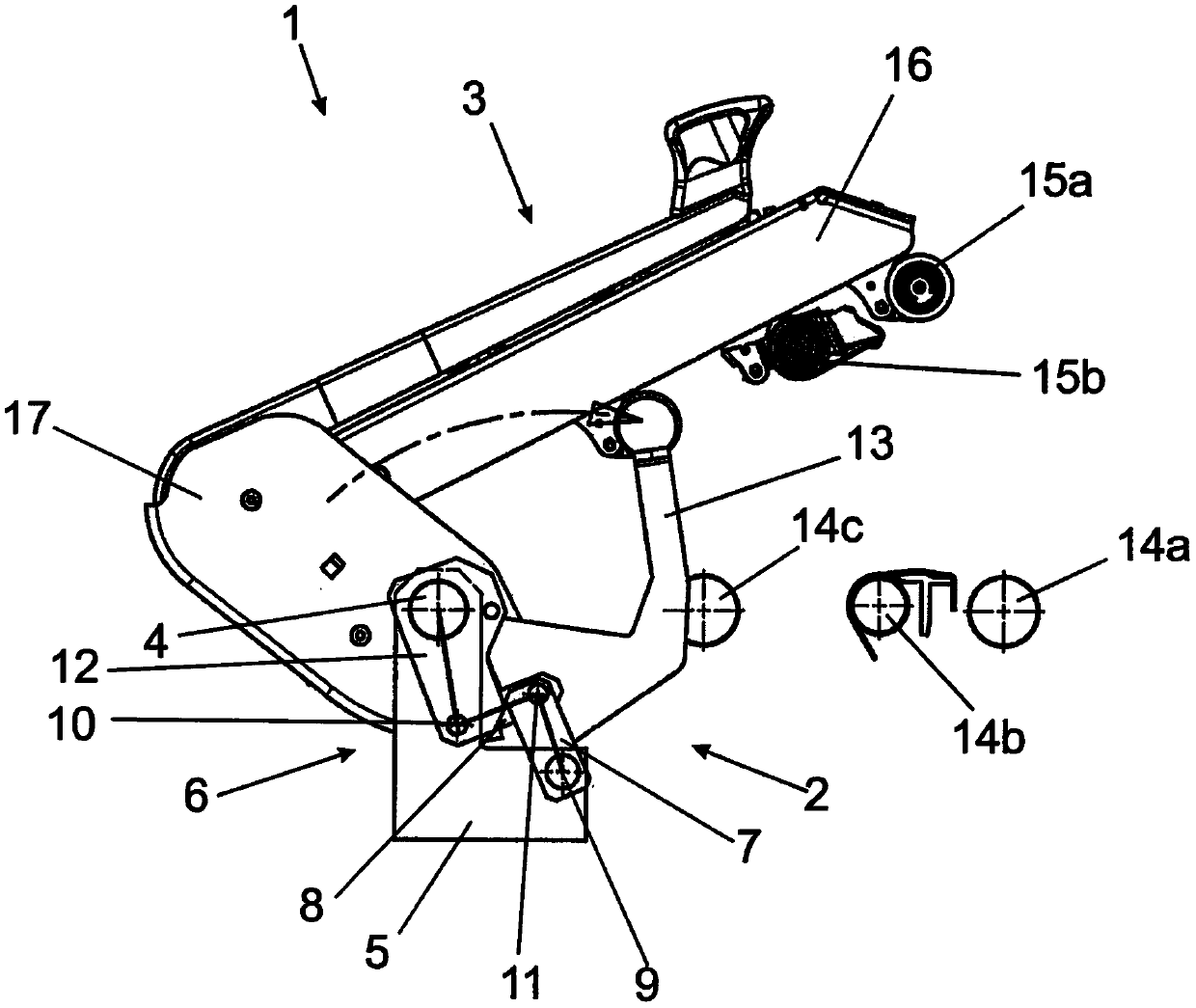
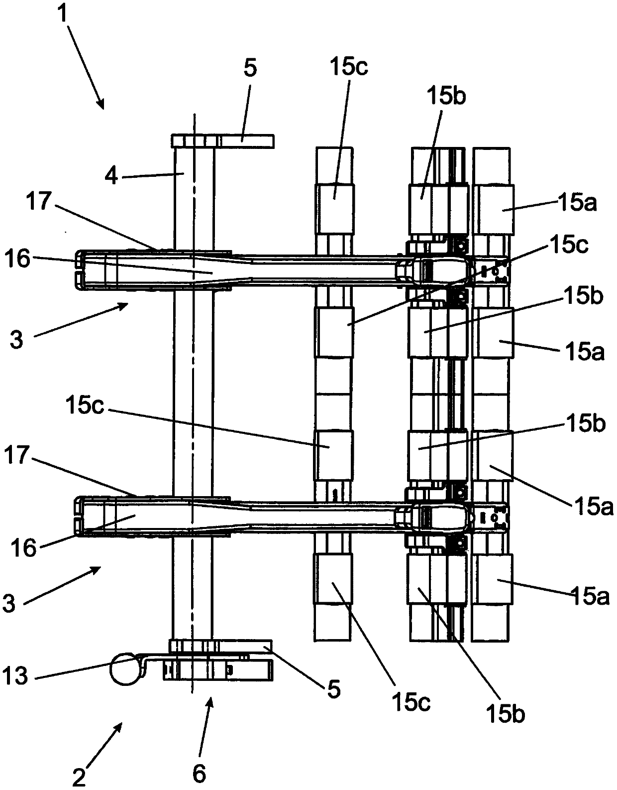
[0039] Spinning machine not shown here such as figure 1 The drafting unit 1 shown is used for the pressure rollers 15a, 15b, 15c and other lower rollers 14a, 14b, 14c which are arranged on the support arms 16 of the pressure saddle 3 of the drafting device which are not shown here. Fiber slivers are drawn between them. To this end, the roller pairs each consisting of a lower roller 14a, 14b, 14c and a pressure roller 15a, 15b, 15c have different rotational speeds that increase in the conveying direction, in order to achieve fiber sliver drafting in the region between the roller pairs. stretch.

[0040] In the exemplary embodiment shown, the drafting unit 1 has two pressurized saddles 3 arranged parallel to each other on the holding rod 4 and each having a support arm 16, each of which has three by two The pair of pressure rollers 15 a , 15 b , 15 c has an axis of rotation extending perpendicularly to the longitudinal axis of the associated support arm 16 . At this point eac...


PUM


Abstract

The invention relates to a drafting system and a drafting system unit for a spinning machine. The drafting system unit has at least one weighting arm, which can be pivoted between an operating position and an open position by a repositioning device. In order to provide a drafting system and a drafting system unit for a drafting system for a spinning machine, the drafting system unit having a particularly simple design and permitting user-friendly operation, it is provided that the at least one weighting arm is connected to a retaining rod for conjoint rotation, which retaining rod is mounted on a retaining rod holder for rotation about the longitudinal axis of the retaining rod by the repositioning device.

Description

technical field [0001] The invention relates to a drafting device for a spinning machine with a drafting device unit and to such a drafting device unit with at least one weighting arm pivotable between a working position and an open position by means of an adjusting device ). Background technique [0002] Various designs of drafting devices for spinning machines are known from the prior art. They are used to draw or stretch the fiber slivers, thereby causing the cross-section of the fibers to be reduced. During drafting, the fibers must move relative to each other as uniformly as possible to obtain a uniform fiber sliver, which is a prerequisite for making a uniform yarn. For drafting the fiber sliver, the drafting device generally has a plurality of successive roller pairs, which tightly clamp the fiber sliver passing between them. In this case, the roller pair usually consists of a driven lower roller and an upper pressure roller which rests against the lower roller. T...

Claims


Application Information

Patent Timeline
Patent Type & Authority Applications(China)
IPC IPC(8): D01H5/56D01H5/48
CPCD01H5/56D01H5/48D01H5/46D01H5/565D01H3/00
Inventor 约阿希姆·迪德里希
Owner SAURER SPINNING SOLUTIONS GMBH & CO KG
Learn More