
Accumulator and hydraulic control system, machine and shifting method having the accumulator

A technology of control system and accumulator, which is applied in the direction of components with teeth, transmission device control, mechanical equipment, etc., can solve problems such as large impact force, vehicle vibration, machine material shaking, etc., to improve the locking ability , Comfortable shifting process, avoiding the effect of shifting impact

Active Publication Date: 2016-02-03
CATERPILLAR INC
View PDF6 Cites 0 Cited by
  • Summary
  • Abstract
  • Description
  • Claims
  • Application Information

AI Technical Summary

Problems solved by technology

For example, in the process of shifting from a forward gear to a reverse gear, the hydraulic transmission control system first releases the pressure quickly, and then the pressure rises rapidly in a very short time, the clutch is engaged rapidly, resulting in a large impact force, the vehicle shakes, and The impact force is likely to cause the material in the machine tool such as the bucket to shake off
The long-term impact of this impact on system components will lead to reduced reliability of the machine's transmission control, poor fault tolerance, reduced service life of components, and shorter maintenance cycles

Method used


Image

  • Accumulator and hydraulic control system, machine and shifting method having the accumulator
  • Accumulator and hydraulic control system, machine and shifting method having the accumulator
  • Accumulator and hydraulic control system, machine and shifting method having the accumulator

Examples


Embodiment Construction

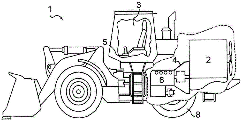
[0022] figure 1 An exemplary machine 1 is shown. The machine 1 may be a mobile machine performing certain tasks related to industries such as mining, construction, farming, transportation, or other industries known in the art. For example, machine 1 may be an earth moving machine, such as a wheel loader, off-road truck, motor grader, or any other earth moving machine. The machine 1 may also be a ship, a passenger vehicle or any other suitable work performing machine. Machine 1 may include a power source 2 , a torque converter 4 and a transmission 6 operatively connected to a traction device 8 . The machine 1 may also include an operator station 3 and one or more operator interface devices 5 for manually controlling the machine 1 .

[0023] The power source 2 can generate a power output, and can be embodied as an internal combustion engine, such as a diesel engine, a gasoline engine, a gas fuel engine, or any other type of engine known to those skilled in the art. The power...


PUM


Abstract

The invention relates to an accumulator for gear shift control, a hydraulic transmission control system and machine with the accumulator, and a gear shifting method, comprising: a housing; and an accumulator capable of sliding in the housing along the axial direction of the housing Piston, the piston has a piston rod and a first piston disc and a second piston disc formed at intervals on the piston rod, a spring engaged with the piston is arranged on the side of the second piston disc away from the first piston disc, the second A piston disc and the housing define a first cavity, and the first piston disc and the second piston disc define a second cavity in the housing; a first channel in fluid communication with the first cavity, and the second cavity The second channel in fluid communication and the third channel located between the first channel and the second channel along the axial direction of the housing, wherein the first, second and third channels communicate with each other in parallel through a common manifold channel, the A part of the main manifold channel connecting the second channel and the third channel is formed with an orifice, and the second channel and the third channel are connected to the hydraulic flow path.

Description

technical field [0001] The invention relates to an accumulator for shift control, and further relates to a hydraulic control system and machine with the accumulator and a gear shift method implemented by the hydraulic control system. Background technique [0002] Machines such as wheel loaders, on- and off-road vehicles, motor graders, and other heavy construction and mining machines are used to perform many jobs. To effectively perform these tasks, these machines require a power source capable of providing power through a transmission to one or more ground engaging devices. The transmission includes a shifting mechanism for producing a mechanically required gear ratio and a hydraulic transmission control system for controlling the shifting mechanism. For example, the shifting mechanism is movable between a plurality of positions, such as: from a first position in which a first gear set is selected to form a first output gear ratio (eg, high speed), to a second position in ...

Claims


Application Information

Patent Timeline
Patent Type & Authority Patents(China)
IPC IPC(8): F16H61/4096
CPCF16H61/0009F16H61/0021F16H61/0267F16H61/0276F16H61/688F16H2061/0034F15B15/02F15B15/24F16H59/02
Inventor 谢发祥南新双张迎军郭金海魏延军邸桂玲
Owner CATERPILLAR INC
Learn More