
Stand-driving type electric carrier

A technology of electric pallet truck and standing driving, which is applied in the direction of lifting device, etc., to achieve the effect of simple and beautiful overall appearance, improved working speed and efficiency, and easy and labor-saving working speed and efficiency

Inactive Publication Date: 2019-12-03
新乡市力力液压设备有限公司
View PDF6 Cites 4 Cited by
  • Summary
  • Abstract
  • Description
  • Claims
  • Application Information

AI Technical Summary

Problems solved by technology

[0004] The purpose of the present invention is to solve the shortcomings of the manual hydraulic shock trucks that are often used in the warehousing and logistics industries in the prior art. People have many inconveniences in the use process and have more urgent needs for improvement, and propose A stand-up electric pallet truck

Method used


Image

  • Stand-driving type electric carrier
  • Stand-driving type electric carrier
  • Stand-driving type electric carrier

Examples


Embodiment 1

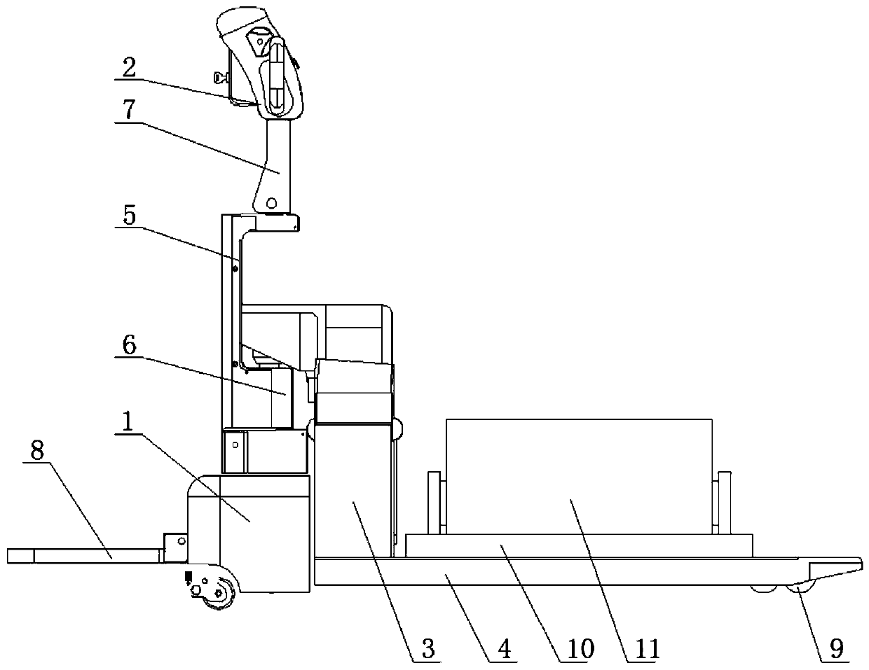
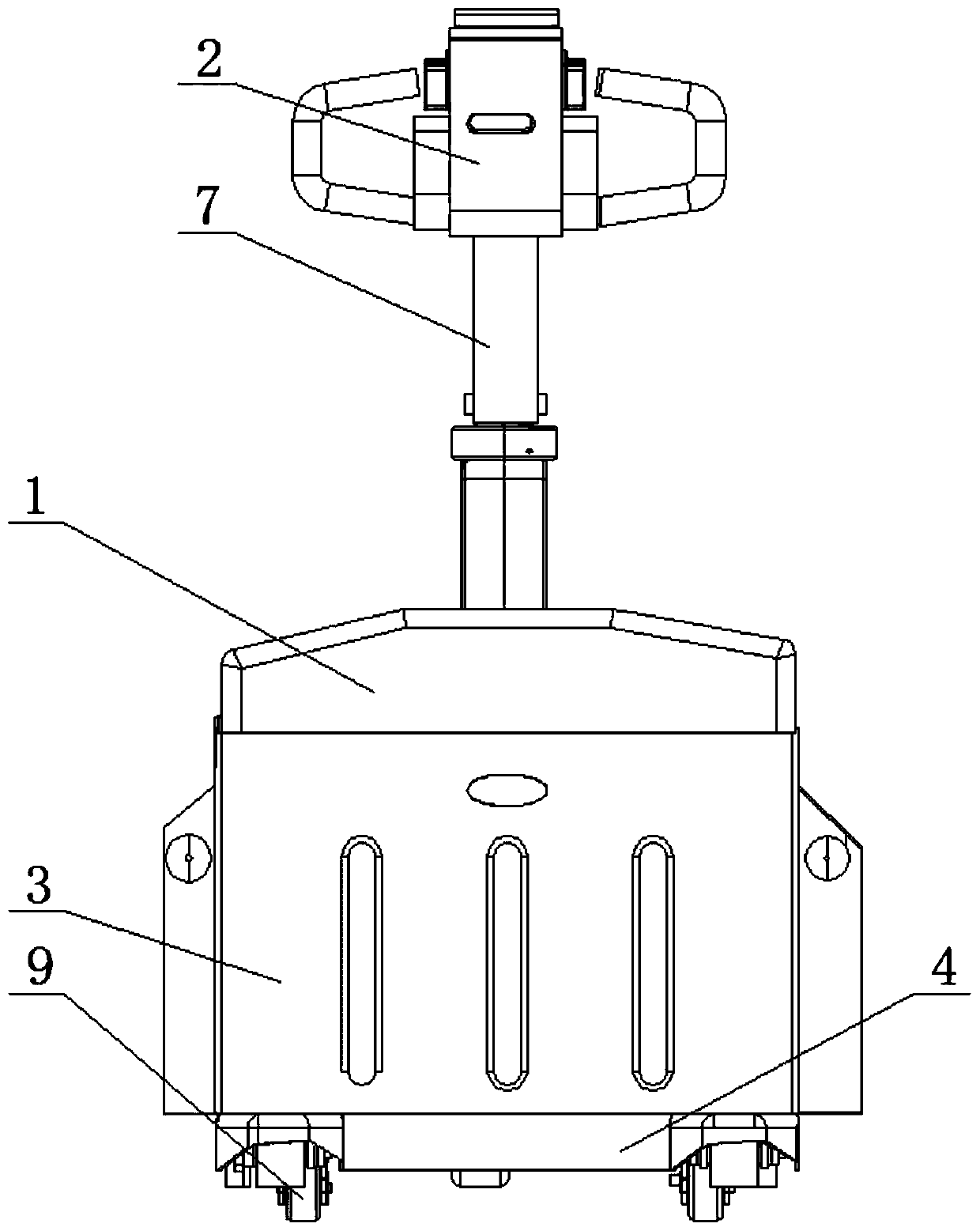
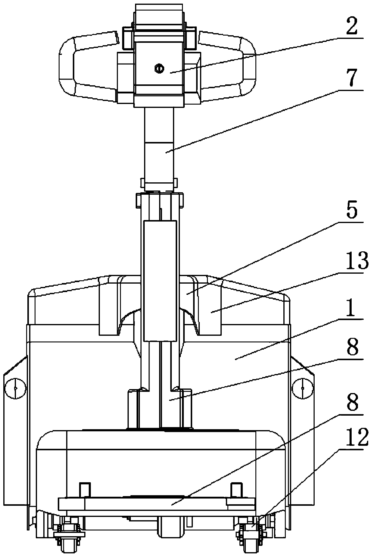
[0023] refer to Figure 1-5 , a stand-up electric transport vehicle, comprising a chassis frame 1, a C-shaped column 5 is arranged on the chassis frame 1, a support plate 3 is slidably connected to one side of the C-shaped column 5, and a cargo is fixedly installed on one side of the support plate 3. The top of the fork 4 is fixed with a fixed seat 10, the top of the fixed seat 10 is clamped with a cargo 11, the chassis frame 1 is provided with a lifting cylinder 6, and the piston rod of the lifting cylinder 6 is fixedly connected with a lifting rod. And the lifting rod is positioned at the bottom of the C-shaped column 5, the top of the lifting rod is fixedly connected with the support plate 3, the top of the C-shaped column 5 is fixedly equipped with a connecting plate 7, and the top of the connecting plate 7 is fixedly equipped with a handle 2, and the handle 2 is provided with There is a control switch, two drive wheels 12 symmetrically arranged are movable installed on th...

Embodiment 2

[0030] refer to Figure 1-5 , a stand-up electric transport vehicle, comprising a chassis frame 1, a C-shaped column 5 is arranged on the chassis frame 1, a support plate 3 is slidably connected to one side of the C-shaped column 5, and a cargo is fixedly installed on one side of the support plate 3. The top of the fork 4 is fixed with a fixed seat 10, the top of the fixed seat 10 is clamped with a cargo 11, the chassis frame 1 is provided with a lifting cylinder 6, and the piston rod of the lifting cylinder 6 is fixedly connected with a lifting rod, And the lifting rod is positioned at the bottom of the C-shaped column 5, the top of the lifting rod is fixedly connected with the support plate 3, the top of the C-shaped column 5 is fixedly equipped with a connecting plate 7, and the top of the connecting plate 7 is fixedly equipped with a handle 2, and the handle 2 is provided with There is a control switch, two drive wheels 12 symmetrically arranged are movable installed on th...


PUM


Abstract

The invention belongs to the technical field of electric trucks, in particular to a stand-driving type electric carrier. In order to solve the problem that for the existing manual hydraulic carriersoften used in storage and logistic industry, more urgent improvement requirements for inconvenience by people in using processes, the invention provides the following scheme: the electric carrier comprises a case frame, a C-shaped stand column is arranged on the case frame. A supporting plate is slidably connected to one side of the C-shaped stand column, a pallet fork is fixedly installed on oneside of the supporting plate, a fixing base is fixedly installed at the top of the pallet fork, goods are clamped to the top of the fixing base, a lifting air cylinder is arranged on the case frame, alifting rod is fixedly connected to a piston rod of the lifting air cylinder, and the lifting rod is located below the C-shaped stand column. According to the electric carrier, the frame of the electric carrier can automatically ascend and descend through the operating handle according to needs so as to control the driving wheels to move, the standing type design is easier and more labor-saving,and the working speed and efficiency are improved.

Description

technical field [0001] The invention relates to the technical field of electric transport vehicles, in particular to a stand-on electric transport vehicle. Background technique [0002] The manual hydraulic pallet truck is a small and convenient, flexible, heavy-duty, durable cargo handling tool, commonly known as "ground cow". In addition to the function of consigning goods, the truck has a hydraulic device between the chassis and the wheels to facilitate the lifting and landing of goods. The goods can be moved by dragging them. After arriving at the destination, the chassis is hydraulically lowered, and the goods also land on the ground, and the truck can be easily pulled out. Save the complicated process of manual handling. It is a good helper for handling goods in the workshop. [0003] With the improvement of the level of social development, people have more urgent needs to improve the inconvenience of the manual hydraulic trucks that are often used in the warehousin...

Claims


Application Information

Patent Timeline
Patent Type & Authority Applications(China)
IPC IPC(8): B66F9/06B66F9/075B66F9/18B66F9/22
CPCB66F9/06B66F9/075B66F9/07513B66F9/18B66F9/22
Inventor 高明松
Owner 新乡市力力液压设备有限公司
Learn More