Three-degree-of-freedom laser mirror adjusting device

A technology for adjusting devices and mirrors, applied in installation, optics, optical components, etc., can solve the problems of increasing the adjustment range, reducing the frequency of readjusting the angle of the mirror mirror, reducing the workload, etc., to improve friction and sensitivity performance, the effect of improving the effect of use

Inactive Publication Date: 2019-11-29
杭州奥创光子技术有限公司
View PDF0 Cites 6 Cited by
  • Summary
  • Abstract
  • Description
  • Claims
  • Application Information

AI Technical Summary

Problems solved by technology

[0005] Aiming at the problems existing in the prior art, the object of the present invention is to provide a three-degree-of-freedom laser mirror adjustment device, which can realize that the mirror can translate along the X axis, swing around the Y axis and rotate around the Y axis during debugging or use. The three parts of the Z-axis swing can be adjusted independently and are highly replaceable. The swing around the Y-axis and the swing around the Z-axis can be adjusted within a large angle of ±10°, and the X-axis direction can be adjusted within a range of 0-5mm. Compared with the existing technology, this device effectively increases the adjustment range. This device ensures that the pitch and side swing are adjusted to the appropriate position through magnet adsorption, and can maintain this state. The whole structure has good shock resistance and the angle is not easy to shift. Compared with the existing technology, it can greatly reduce the displacement caused by external interference, so that the position of the reflective lens is not easy to have angle deviation during use, thereby improving the use effect and reducing the angle readjustment of the reflective lens frequency, reducing workload

Method used


Image

  • Three-degree-of-freedom laser mirror adjusting device
  • Three-degree-of-freedom laser mirror adjusting device
  • Three-degree-of-freedom laser mirror adjusting device

Examples


Embodiment 1

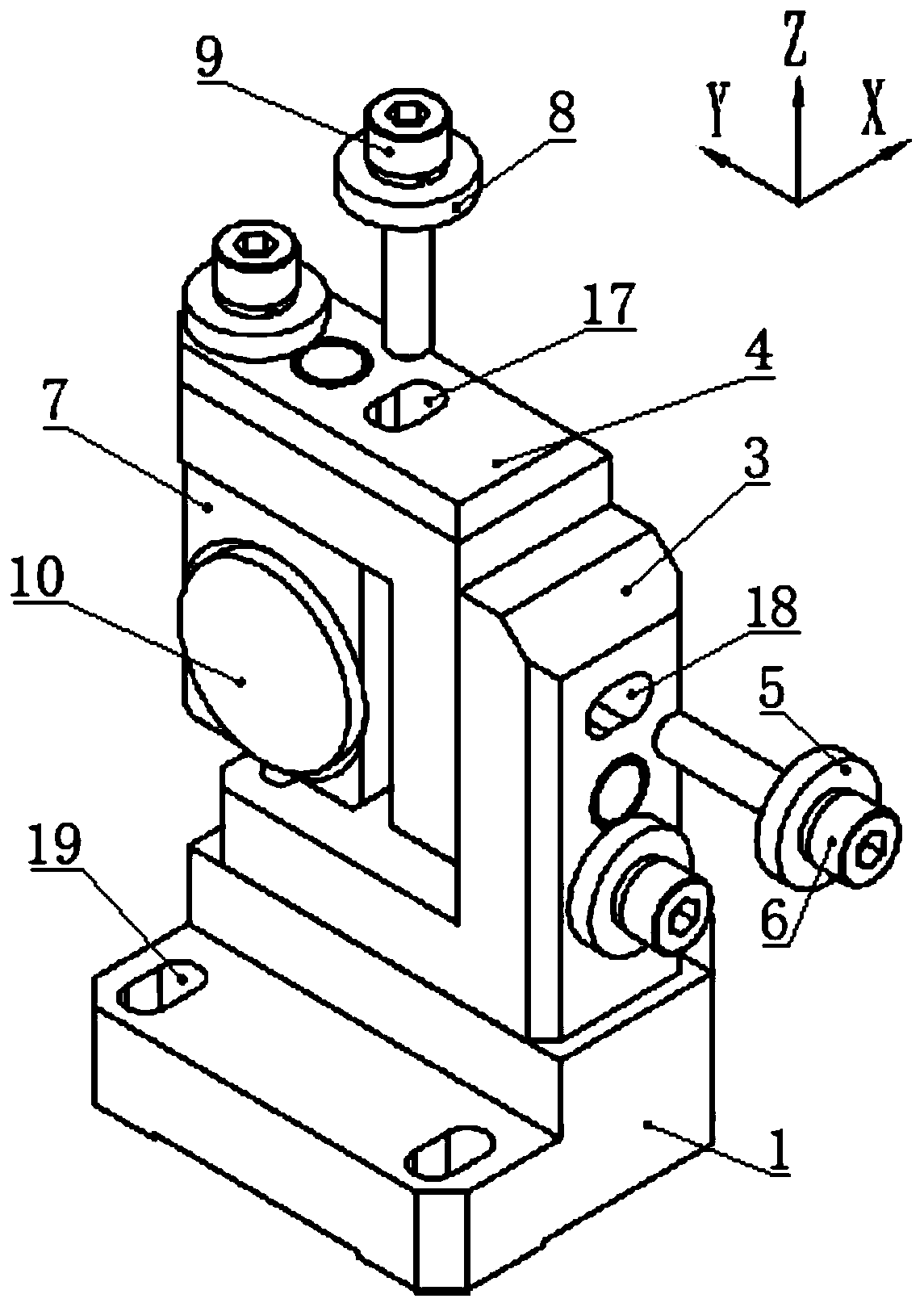
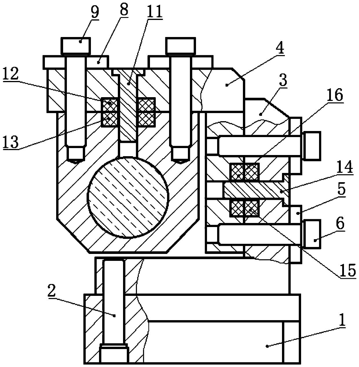
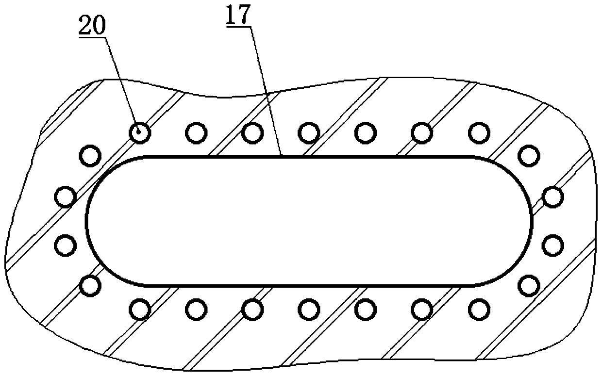
[0041] see Figure 1-2 , a three-degree-of-freedom laser mirror adjustment device, including a base 1, two base waist holes 19 are dug above the base 1, the upper end of the base 1 is fixedly connected with a support frame 3 through a connecting screw 2, and the connecting screw 2 Fix the support frame 3 on the base 1. The base waist hole 19 on the base 1 can fix the whole device in the optical table or laser product. The base waist hole 19 can also be fine-tuned on the X-axis, supporting The left end of the frame 3 is provided with a pitch adjustment frame 4, and a right magnetic suction plate is arranged between the support frame 3 and the pitch adjustment frame 4, and two symmetrical support frame arc waist-shaped holes 18 are cut at the right end of the support frame 3, and the support frame 3 and the The corresponding positions of the pitch adjustment frame 4 are drilled with right positioning pin holes, and the right positioning pin holes are located between the two supp...


PUM


Abstract

The invention discloses a three-degree-of-freedom laser reflector adjusting device, and belongs to the technical field of optical element azimuth adjustment. The three-degree-of-freedom laser reflector adjusting device can realize that three parts of translation along an X axis, swinging around a Y axis and swinging around a Z axis can be independently adjusted in the debugging or using process ofa reflector, the replaceability is strong, the swinging around the Y axis and the swinging around the Z axis can be adjusted within a large angle range of +/-10 degrees, and the X axis direction canbe adjusted within a range of 0-5 mm. Compared with the prior art, the three-degree-of-freedom laser reflector adjusting device effectively enlarges the adjusting range, simultaneously, and after thepitching and the side swinging are adjusted to proper positions in a magnet adsorption mode, the state can be kept for positioning, and compared with the prior art, the condition that the reflector generates displacement due to external interference can be greatly reduced, and furthermore the position of the reflector is not easy to generate angular deviation in the using process, and then the result of use is further improved, the frequency of carrying out the angle readjustment to the reflector is reduced, and the work load is reduced.

Description

technical field [0001] The invention relates to the technical field of orientation adjustment of optical elements, and more specifically relates to a three-degree-of-freedom laser mirror adjustment device. Background technique [0002] The laser reflector is a component used to turn the optical path of the laser system. At present, most of the reflectors sold on the market use simple open mirror frames to install the reflectors on the equipment. Similarly, there are reflectors in the laser, and the optical path is extended through the reflectors to reduce the volume of the laser. It is fixedly installed on the reflector bracket. When the reflector bracket is fixedly installed on the bottom plate of the laser, the reflector cannot be adjusted. The purpose of this is to ensure the accuracy of the reflector and prevent it from changing during use, resulting in reflection The offset of the optical path, but for accurate reflection, it takes a lot of time to adjust the position ...

Claims


Application Information

Patent Timeline
Patent Type & Authority Applications(China)
IPC IPC(8): G02B7/182
CPCG02B7/1821
Inventor 杨直何哲魏玉凤张雷
Owner 杭州奥创光子技术有限公司
Why Eureka
Try Eureka