Turbine lifting device used for ship machining

A lifting equipment and turbine technology, applied in the direction of cranes, trolley cranes, walking mechanisms, etc., can solve the problems of limited lifting weight of boom-type lifting equipment, inability to move flexibly, time-consuming and laborious maintenance, etc. Heavy weight and flexibility, achieve flexibility, improve the effect of lifting weight

Inactive Publication Date: 2019-11-26
BINZHOU POLYTECHNIC
View PDF10 Cites 1 Cited by
  • Summary
  • Abstract
  • Description
  • Claims
  • Application Information

AI Technical Summary

Problems solved by technology

[0002] When a ship is being processed, manufactured or maintained, due to the large volume and weight of the ship's turbine equipment or other equipment, generally the passenger ship does not have its own lifting equipment, and the lifting equipment of the cargo ship generally adopts the boom type for loading and unloading cargo. There are two types of lifting equipment and cranes. The lifting weight of boom-type lifting equipment is limited, and both types of lifting equipment have the problem of fixed position and no way to move flexibly. There is no way to load and unload large equipment such as turbines on ships. It is necessary to park the ship in a fixed port, and use large-scale lifting equipment such as gantry cranes on land to operate, which results in time-consuming and labor-intensive maintenance, a waste of labor, and high maintenance costs; The lifting equipment is the problem that needs to be solved

Method used


Image

  • Turbine lifting device used for ship machining
  • Turbine lifting device used for ship machining
  • Turbine lifting device used for ship machining

Examples


Embodiment Construction

[0018] The technical solutions in the embodiments of the present invention will be described clearly and completely in further detail below in conjunction with the accompanying drawings in the embodiments of the present invention. Based on the embodiments of the present invention, all other embodiments obtained by persons of ordinary skill in the art without making creative efforts belong to the protection scope of the present invention.

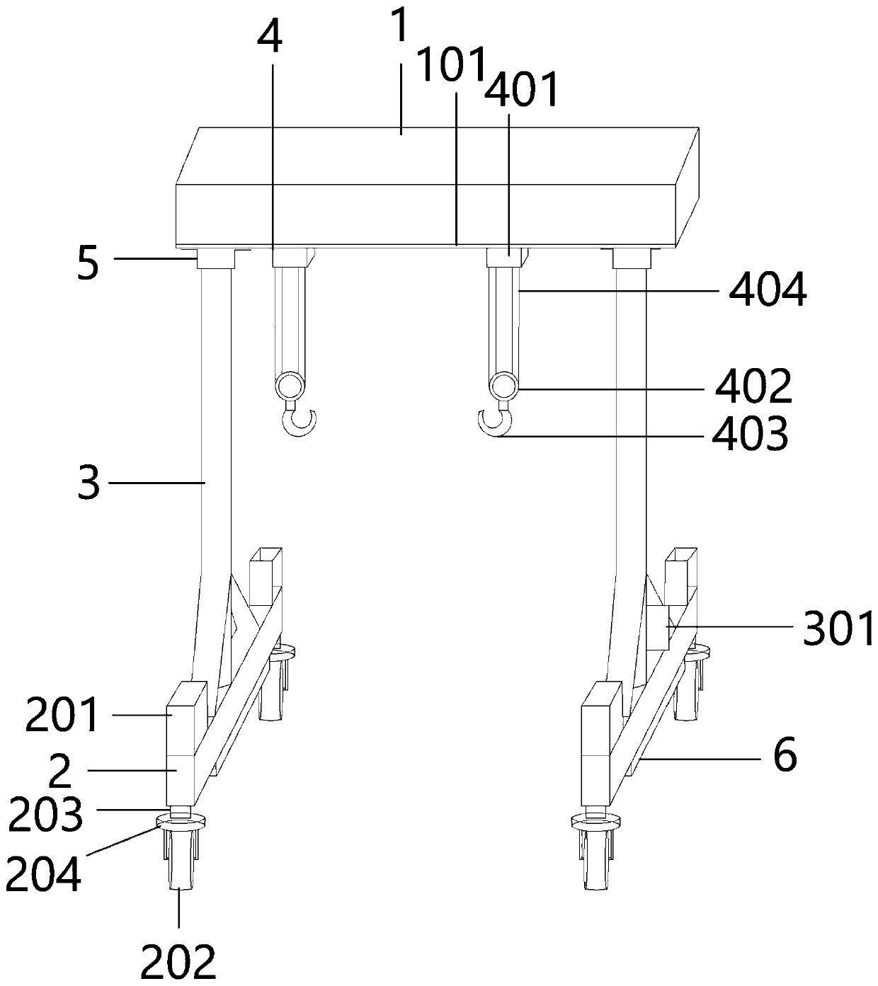
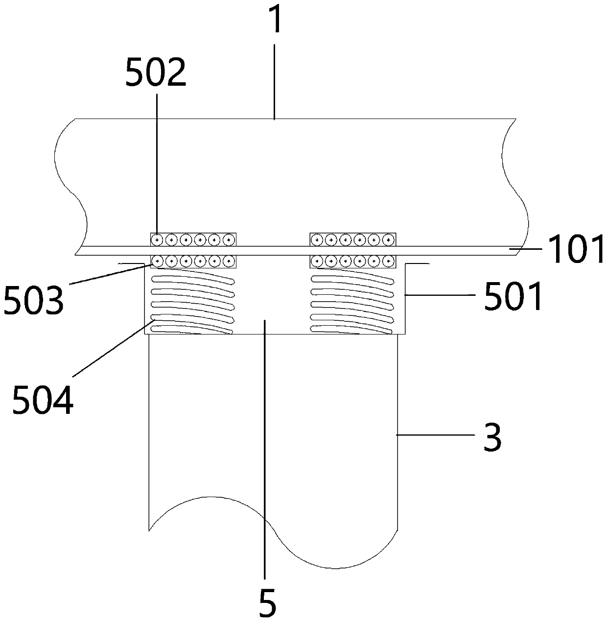
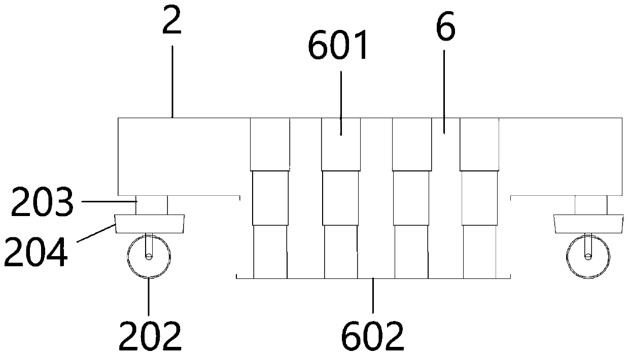
[0019] Such as Figure 1-3 As shown, a turbine lifting device for ship processing includes two traveling girders 3, a main beam 1 connected to the upper part of the traveling girders 3, and a base 2 fixed to the lower part of the traveling girders 3. The lower part of the main girder 1 is provided with Slide rail 101, slide rail 101 is slidably connected to the traveling mechanism 5 on the upper end of the walking beam 3, the traveling mechanism 5 is provided with a housing 501 with a distance from the main beam 1, and a plurality of housing...


PUM


Abstract

The invention provides a turbine lifting device used for ship machining. The turbine lifting device comprises two walking supporting beams, a main beam connected to the upper portions of the walking supporting beams and bases fixed to the lower portions of the walking supporting beams. A sliding rail is arranged at the lower portion of the main beam, and the sliding rail is connected with walkingmechanisms fixed to the upper ends of the walking supporting beams in a sliding manner. Each walking mechanism is provided with a shell body spaced with the main beam, wherein multiple supporting springs making the shell body spaced with the main beam are fixed to the bottom of the inner side of the shell body, multiple lower walking wheels located below the sliding rail are connected to the upperends of the supporting springs, and upper walking wheels are connected to the positions, corresponding to the lower walking wheels, above the sliding rail. By means of the turbine lifting device usedfor ship machining, due to the designed walking mechanisms and wheels, the whole lifting device can be moved flexibly, meanwhile, the two walking supporting beams move along the sliding rail, and therefore the turbine lifting device can adapt to various narrow walking and working environments; the supporting springs are arranged below the lower walking wheels of the walking mechanisms, so that friction between the shell bodies and the main beam is avoided; and due to designed bearing devices, the lifting weight and flexibility of the lifting device are improved.

Description

technical field [0001] The invention relates to the technical field of lifting equipment, in particular to a turbine lifting equipment for ship processing. Background technique [0002] When a ship is being processed, manufactured or maintained, due to the large volume and weight of the ship's turbine equipment or other equipment, generally the passenger ship does not have its own lifting equipment, and the lifting equipment of the cargo ship generally adopts the boom type for loading and unloading cargo. There are two types of lifting equipment and cranes. The lifting weight of boom-type lifting equipment is limited, and both types of lifting equipment have the problem of fixed position and no way to move flexibly. There is no way to load and unload large equipment such as turbines on ships. It is necessary to park the ship in a fixed port, and use large-scale lifting equipment such as gantry cranes on land to operate, which results in time-consuming and labor-intensive mai...

Claims


Application Information

Patent Timeline
Patent Type & Authority Applications(China)
IPC IPC(8): B66C19/00B66C13/40B66C9/08
CPCB66C9/08B66C13/40B66C19/00
Inventor 翟伟陆宝成赵志强孙庆云
Owner BINZHOU POLYTECHNIC
Why Eureka
Try Eureka