Directional loudspeaker

A technology of directional speakers and centering brackets, applied in the field of speakers, can solve problems such as disturbing residents, speaker interference, and interference, and achieve the effect of improving user experience

Inactive Publication Date: 2019-11-22
平阳县然亿贸易有限公司
View PDF5 Cites 0 Cited by
  • Summary
  • Abstract
  • Description
  • Claims
  • Application Information

AI Technical Summary

Problems solved by technology

[0002] Loudspeakers are an important part of audio equipment, which can convert audio electrical signals into acoustic signals that can be heard by the human ear, thereby transmitting more information to users; loudspeakers are fully used in all walks of life: such as commercial places, The seller will play the product information, price and preferential activities through the loudspeaker in a loop, which is convenient for customers to choose according to their needs; in museums and memorial halls, the loudspeaker will introduce the information, age, value, background and other information of the collection to the audience, so that the audience can understand the products in the collection and history, so as to better understand the collection; in the streets and squares, aunts play dynamic music through speakers, follow the music to move their muscles and bones, and keep fit; it can be said that speakers have become an indispensable part of modern life; but in these use In some occasions, the loudspeaker will cause a lot of interference. For example, various products in the mall are playing at the same time, and customers who have no needs around them will feel noisy; audiences in the museum who are not near the collection will also receive a lot of information, which will undoubtedly become interference. ; The square dance music of aunts often disturbs the residents resting around

Method used


Image

  • Directional loudspeaker

Examples


Embodiment

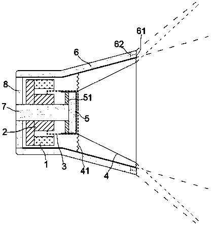
[0016] exist figure 1 In the illustrated embodiment, the directional loudspeaker includes a housing, a permanent magnet 1, a stem 2, a voice coil 3, a cone 4, and a centering bracket 41; the stem 2, the voice coil 3, and the permanent magnet 1 are all Shaft setting, the paper cone 4 is set at one end of the voice coil 3, and the other end of the voice coil 3 can reciprocate in the gap between the stem 2 and the permanent magnet 1; the voice coil 3 is limited by the centering bracket 41 connected to the housing;

[0017] It also includes a cutting tube 5 and an anti-phase sound cavity 6; the cutting tube 5 is fixedly arranged on the inner wall of the voice coil 3; cover 51;

[0018] A conduction cylinder 7 is arranged on the sealing cover 51, and the conduction cylinder 7 penetrates the stem 2 from the axis of the stem 2;

[0019] The anti-phase sounding cavity 6 is sleeved on the outside of the casing in the shape of a ring, and the anti-phase sounding cavity 6 includes an ...


PUM


Abstract

The invention relates to a directional loudspeaker which comprises a shell, a permanent magnet, a core column, a voice coil, a cone and a centering support. The silencer further comprises a reductioncylinder and a reverse-phase sound production cavity. The reduction cylinder is fixedly arranged on the inner wall of the voice coil; one end of the reduction cylinder is closed, and a sealing cover is arranged on the cylinder wall of the reduction cylinder in a sliding mode. A conduction cylinder is arranged on the sealing cover and penetrates through the core column from the axis of the core column; the reverse-phase sounding cavity comprises a reverse-phase vibrating diaphragm, and the reverse-phase vibrating diaphragm and the paper cone face the same direction; a conduction pipe is connected between the reverse-phase sound production cavity and the conduction cylinder, and the reverse-phase sound production cavity, the conduction pipe, the conduction cylinder and the reduction cylinderform a closed air cavity; the directional loudspeaker is novel in structure and unique in principle, the broadcasting range of the loudspeaker can be gathered within a small range, and therefore thedirectional playing effect is achieved, only information is transmitted to target audiences, interference to other residents is avoided, and the use experience is improved.

Description

technical field [0001] The invention relates to the field of loudspeakers, in particular to a loudspeaker with a specific propagation angle. Background technique [0002] Loudspeakers are an important part of audio equipment, which can convert audio electrical signals into acoustic signals that can be heard by human ears, so as to transmit more information to users; loudspeakers are fully used in all walks of life: such as commercial places, The seller will play the product information, price and preferential activities through the loudspeaker in a loop, which is convenient for customers to choose according to their needs; in museums and memorial halls, the loudspeaker will introduce the information, age, value, background and other information of the collection to the audience, so that the audience can understand the products in the collection and history, so as to better understand the collection; in the streets and squares, aunts play dynamic music through speakers, follo...

Claims


Application Information

Patent Timeline
Patent Type & Authority Applications(China)
IPC IPC(8): H04R9/06H04R9/02
CPCH04R9/02H04R9/06
Inventor 朱虹斐
Owner 平阳县然亿贸易有限公司
Why Eureka
Try Eureka