
Layered rotary cutting test device and test method for adhesion near interface with volume change being restrained

A testing device and testing method technology, applied in the direction of measuring device, using stable torsional force to test material strength, using stable shear force to test material strength, etc. Problems such as position and stress state, inability to control the depth of rotary cutting to keep constant, etc., to achieve the effect of reducing friction

Pending Publication Date: 2019-11-22
NANJING FORESTRY UNIV
View PDF0 Cites 0 Cited by
  • Summary
  • Abstract
  • Description
  • Claims
  • Application Information

AI Technical Summary

Problems solved by technology

[0005] In summary, the existing technology has the following disadvantages: ①The shear failure surface is relatively fixed, which cannot reflect the position and stress state of the real shear surface; ②The influence of the residual soil layer near the interface layer on the adhesion force is ignored; ③It cannot be measured Interfacial delamination adhesion under the rotary cutting distance, or the depth of rotary cutting cannot be well controlled to keep constant within a small error

Method used


Image

  • Layered rotary cutting test device and test method for adhesion near interface with volume change being restrained
  • Layered rotary cutting test device and test method for adhesion near interface with volume change being restrained
  • Layered rotary cutting test device and test method for adhesion near interface with volume change being restrained

Examples


Embodiment Construction

[0030] The present invention will be further described below in conjunction with the accompanying drawings and embodiments.

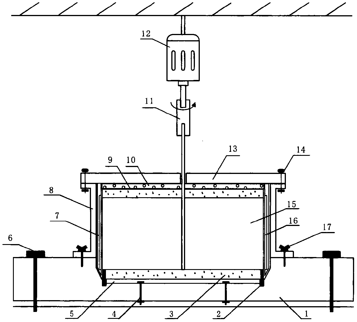
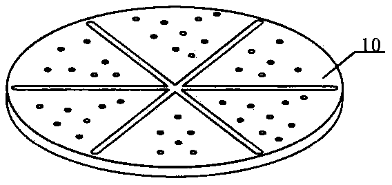
[0031] A kind of adhesion force layering rotary cutting test device near the interface of constrained volume change (such as figure 1 ), including grooved base 1, metal washer 2, soil sample 3, pin 14, metal bottom plate 5, bolt 6, ring knife 7, wall protection cylinder 8, filter paper 9, permeable plate 10, torque meter 11, drive power supply 12. The pressure cover plate 13, the pin bolt II 14, the rotary cutting plate 15, the sliding ring 16 and the pin bolt III 17 are jointly composed;

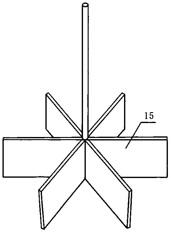
[0032] Rotary cutting plate 15 (such as figure 2 ) side close to ring knife 7 inside sliding ring 16 (such as Figure 4 ), which eliminates the adhesion resistance of the ring knife to the rotary cutting plate (15) during rotary cutting, and the angle between the blades is small. After the rotary cutting is completed, a large amount of soil can be taken away to cl...


PUM


Abstract

The invention provides a layered rotary cutting test device and test method for adhesion near an interface with volume change being restrained. The device is formed by a base with a groove, a metal washer, a soil sample, bolt pins I-III, a metal bottom plate, bolts, a ring cutter, a wall protection cylinder, filter paper, a water permeable plate, a torque meter, a driving power supply, a pressurization cover plate, a rotary cutting plate and a sliding ring. The distance between the rotary cutting plate and the metal bottom plate is changed through the metal washer, the driving power supply drives the rotary cutting plate at different constant speeds, and shear load is recorded by the torsion meter, thereby realizing a function of testing the shear load of the soil sample sheared at different speeds under different rotary cutting distances; the setting of the metal washer effectively solves the problem of changing the micro rotary cutting spacing between the rotary cutting plate and themetal bottom plate; and the setting of the wall protection cylinder effectively solves the problem of observing the soil sample shear damage characteristics on the metal bottom plate after test. Thelayered rotary cutting test method for adhesion near the interface with the volume change being restrained is an effective method for studying rotary cutting adhesion near the interface and adhesion difference characteristics.

Description

technical field [0001] The invention belongs to the technical field of tunnel and underground engineering test instruments, and in particular relates to a layered rotary cutting test device and a test method for adhesion force near an interface that constrains volume changes. Background technique [0002] Soil adhesion generally exists in the construction of underground engineering, especially in the construction machinery of urban tunnels. The shield cutterhead often encounters clay clogging and adhesion machinery in the process of rotary cutting soil, which leads to the torque of the cutterhead. Increase, damage machinery, reduce controllability of shield tunneling and delay construction progress. [0003] How to reduce the sticking phenomenon of the cutter head in shield tunneling construction is an important subject to be studied and solved urgently. The study of the peeling adhesion and adhesion difference characteristics near the contact interface between cohesive soi...

Claims


Application Information

Patent Timeline
IPC IPC(8): G01N19/04G01N3/24G01N3/22G01N3/02
CPCG01N19/04G01N3/24G01N3/02G01N3/22G01N2203/0025G01N2203/0026G01N2203/0676
Inventor 刘成肖宇豪张敬宇殷孝天黄琳马天龙
Owner NANJING FORESTRY UNIV
Learn More