Eureka AIR delivers breakthrough ideas for toughest innovation challenges, trusted by R&D personnel around the world.

Intelligent control system for flue gas waste heat utilization of thermal power generation unit

A technology for thermal power generating units and intelligent control systems, applied in control systems, steam generation, indirect heat exchangers, etc., can solve the problems of low heat utilization efficiency, poor control effect, cumbersome operation, etc. Effect

Active Publication Date: 2019-11-22
GUODIAN NEW ENERGY TECH INST
View PDF5 Cites 2 Cited by
  • Summary
  • Abstract
  • Description
  • Claims
  • Application Information

AI Technical Summary

Problems solved by technology

Chinese Invention Patent No. 201510315237.3 provides an energy-saving and low-dust emission coal-fired thermal power generation system. Embodiment 1 provides a waste heat recovery system. This system provides a technical solution for intelligent control of the waste heat of the flue gas of the dynamic generator set. But the utilization efficiency of residual heat is low
In the prior art, various valve openings and water pump start and stop are manually operated to meet the control requirements, which not only requires a lot of manpower, but also is cumbersome to operate, the control effect is not good, and it is not conducive to the economic operation of the system.

Method used


Image

  • Intelligent control system for flue gas waste heat utilization of thermal power generation unit
  • Intelligent control system for flue gas waste heat utilization of thermal power generation unit
  • Intelligent control system for flue gas waste heat utilization of thermal power generation unit

Examples


Embodiment Construction

[0032] The specific embodiments of the present invention will be described below with reference to the accompanying drawings.

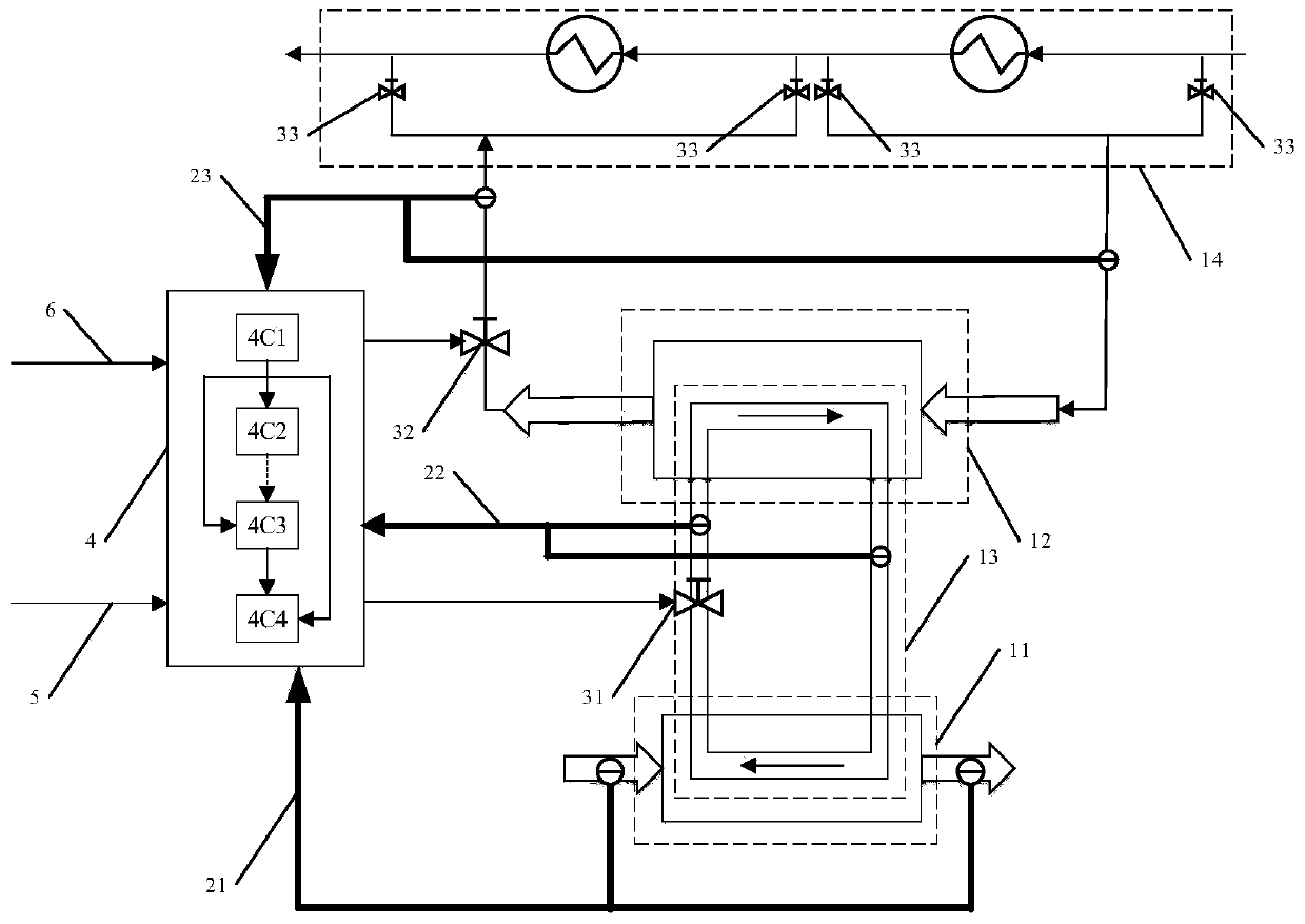
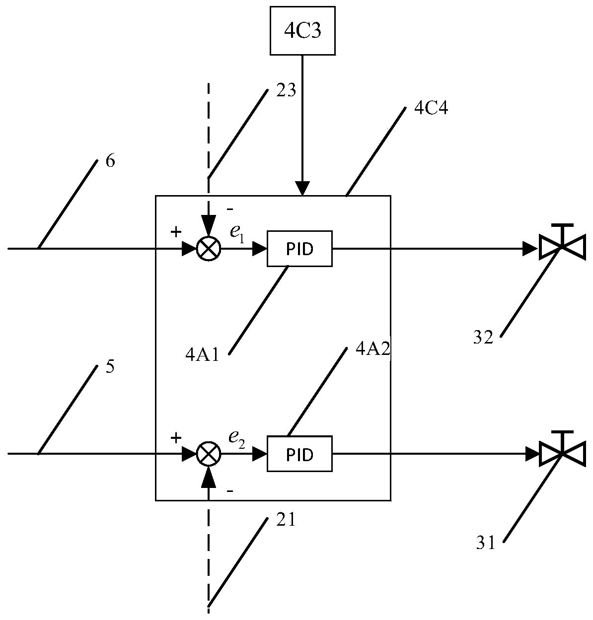
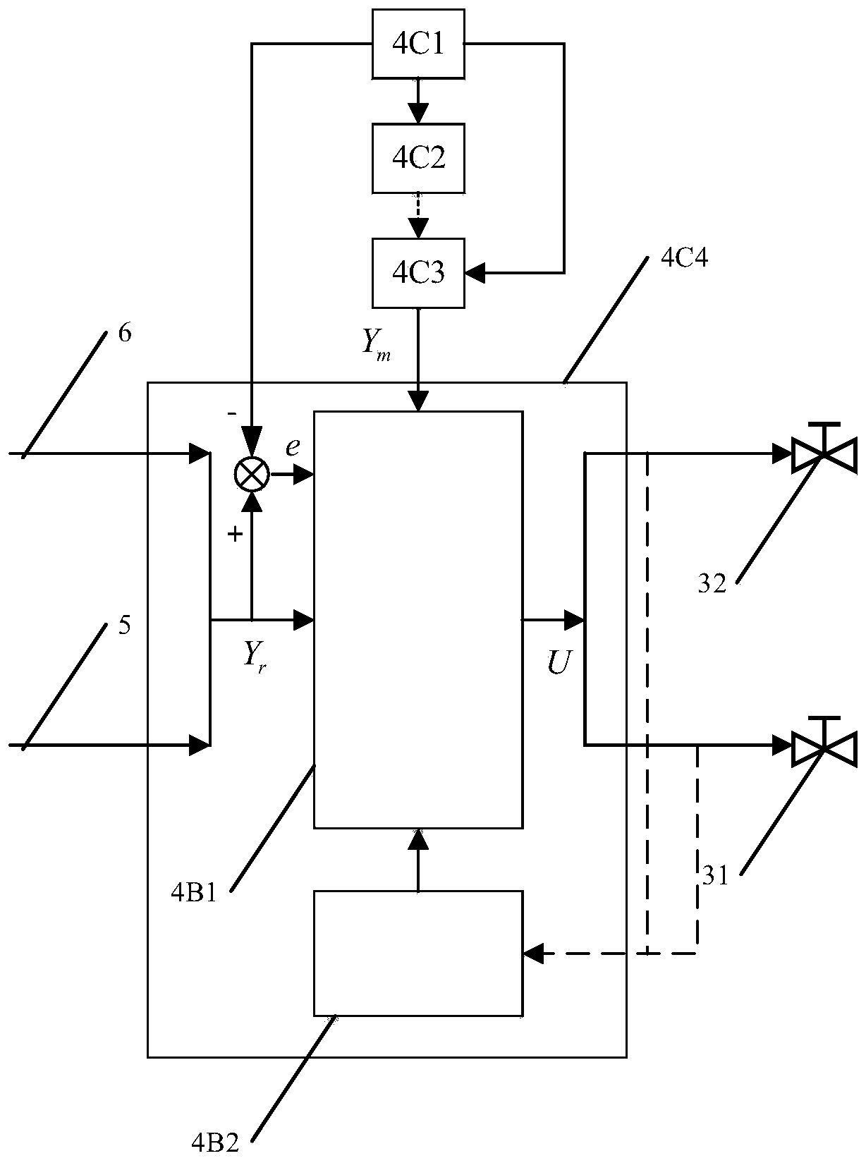
[0033] like figure 1 As shown, it is a schematic structural diagram of the intelligent control system for the utilization of flue gas waste heat of the thermal power generating set of the present invention. The intelligent control system for the utilization of flue gas waste heat includes a heat exchange structure 1, a measurement and sensing structure 2, a heat exchange optimization structure 3 and an optimization control structure 4. .

[0034]The heat exchange structure 1 includes a tube heat exchanger 11 , a non-contact cooler 12 , a circulating water system 13 and a condensed water heat exchange system 14 . The tube heat exchanger 11 is arranged on the flue of the thermal power generation unit. The tube heat exchanger 11 is divided into a tube side and a shell side. The circulating water of the cooler 12 and the circulating water system 13. Th...


PUM


Abstract

The invention relates to an intelligent control system for flue gas waste heat utilization of a thermal generator unit. The system is provided with a heat exchange structure, a measurement sensing structure, a heat exchange optimization structure and an optimization control structure. The heat exchange structure can recover the waste heat of high-temperature flue gas at the tail of a boiler, and sends the waste heat to a condensation water heat exchange system through the intermediate heat exchange of a circulating water system. Based on parameters such as temperature and flow of flue gas, circulating water and condensate water, real-time feedback and calculation analysis are carried out on the waste heat utilization scheme. With maximum utilization of flue gas waste heat as a target, thecondensate water inlet / outlet position, circulating water flow and condensate water flow are adjusted to realize intelligent control of a waste heat utilization system, so that flue gas waste heat isrecycled and is fully used for assisting a steam turbine heater of the thermal power generating unit.

Description

technical field [0001] The invention belongs to the technical field of environmental protection equipment, and in particular relates to an intelligent control system for the utilization of waste heat from flue gas of a thermal power generating set. Background technique [0002] The exhaust gas temperature of the thermal power generating unit affects the economy and safety of the boiler. At the same time, boiler exhaust heat loss accounts for more than half of the boiler heat loss. Reducing the exhaust heat loss through the utilization of flue gas waste heat is one of the important ways to reduce the energy consumption of power plant boilers. [0003] The boiler flue gas waste heat recovery equipment is arranged in the tail flue where the flue gas temperature is relatively low. Chinese Invention Patent No. 201510315237.3 provides an energy-saving and low-dust emission coal-fired thermal power generation system, wherein the first embodiment provides a waste heat recovery syst...

Claims


Application Information

Patent Timeline
IPC IPC(8): F22B31/08F23J15/06F28D7/00G01D21/02F22B35/00
CPCF22B31/08F22B35/00F23J15/06F28D7/00G01D21/02Y02E20/30
Inventor 陈保卫刘淼梁凌李庚达
Owner GUODIAN NEW ENERGY TECH INST
Why Eureka
Eureka Blog
Learn More