Eureka AIR delivers breakthrough ideas for toughest innovation challenges, trusted by R&D personnel around the world.

Temperature control device and method for centrifugal casting

A technology of a temperature control device and a temperature control method, which is applied in the field of centrifugal casting temperature control, can solve problems such as large temperature differences in the working layer, achieve precise control, and improve casting quality.

Active Publication Date: 2021-12-07
LINYI TIANKUO CASTING CO LTD
View PDF8 Cites 2 Cited by
  • Summary
  • Abstract
  • Description
  • Claims
  • Application Information

AI Technical Summary

Problems solved by technology

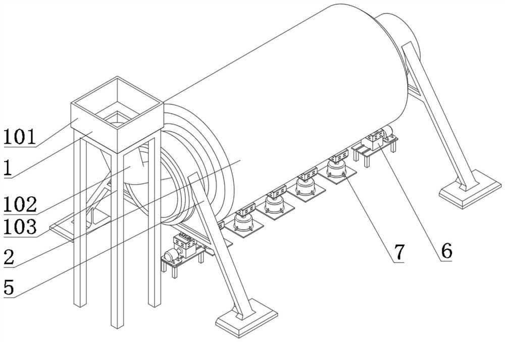
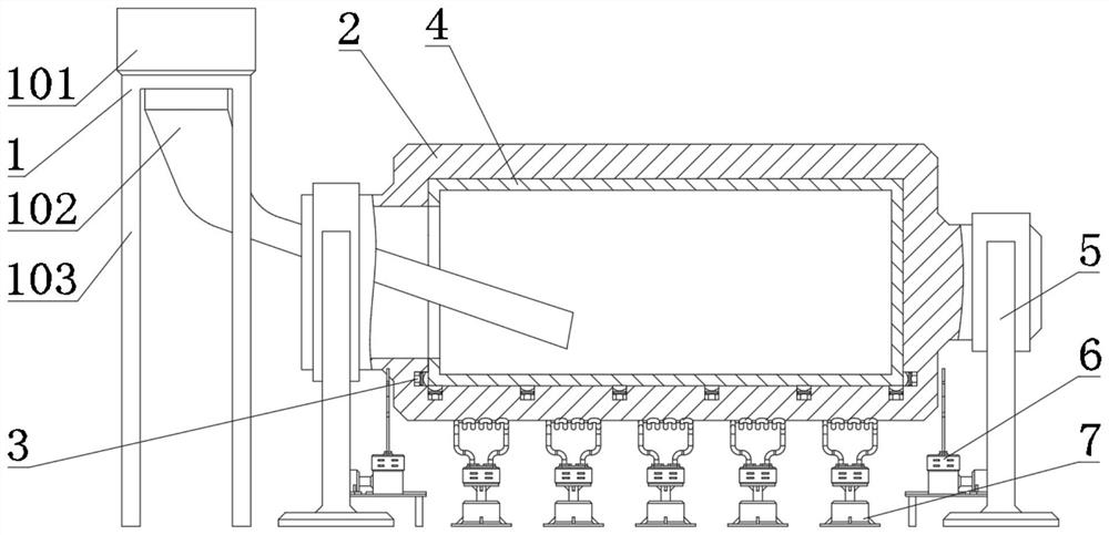
[0004] In view of the above problems, the object of the present invention is to provide a centrifugal casting temperature control device and its method, which uses multiple sets of temperature detection devices to measure the temperature change during casting, and controls the side heating device and the cylinder heating device according to the corresponding temperature relationship Data-based and controllable heating is carried out on the corresponding parts, which realizes the temperature difference control of centrifugal casting, and effectively solves the problem of excessive temperature difference between different casting metals and formed working layer parts and the working layer itself during composite roll casting

Method used


Image

  • Temperature control device and method for centrifugal casting
  • Temperature control device and method for centrifugal casting
  • Temperature control device and method for centrifugal casting

Examples


Embodiment Construction

[0035] In order to more clearly illustrate the technical solutions in the embodiments of the present invention or the prior art, the following will briefly introduce the drawings that need to be used in the description of the embodiments or the prior art. Obviously, the accompanying drawings in the following description These are some embodiments of the present invention. Those skilled in the art can also obtain other drawings based on these drawings without creative work.

[0036] It should be noted that in the description of the present invention, the terms "upper", "lower", "top", "bottom", "side", "other side", "left", "right" etc. indicate The orientation or positional relationship is based on the orientation or positional relationship shown in the drawings, and is only for the convenience of describing the present invention and simplification of the description, and does not mean that devices or elements must have a specific orientation, be constructed and operated in a s...


PUM


Abstract

The invention relates to a temperature control device and a method for centrifugal casting, and the temperature control device detects the temperature of a working layer of a roller during casting through a plurality of groups of temperature detection devices, and carries out temperature compensation on the working layer through a side heating device and a cylindrical surface heating device. According to the method for centrifugal casting, the casting temperature of the cylindrical surface, the casting temperature of the side surface and the casting temperature of the center are compared and calculated, the distance between a heating coil and the outer wall of a mold is adjusted and controlled through the temperature difference, and centrifugal casting temperature control is achieved; the problem that the temperature difference between different casting metals and a formed working layer part and the temperature difference between working layers are too large during casting of a composite roller is effectively solved. According to the temperature control device and the method for centrifugal casting, the temperature difference regulation and control of different casting metals, formed working layer parts and working layers during casting of the composite roller are realized, and the cylindrical surface temperature difference and the edge temperature difference of the working layers of the composite roller can be effectively regulated and controlled; and meanwhile, the temperature difference of the working layers of the composite roller in the casting process is precisely regulated and controlled, and the casting quality of the working layers of the composite roller is improved.

Description

technical field [0001] The invention relates to the technical field of centrifugal casting temperature control, in particular to a centrifugal casting temperature control device and a method thereof. Background technique [0002] Commonly used composite rolls are wear-resistant rolls in which the outer layer of the roll is made of high-hardness wear-resistant materials, and the middle core is made of high-strength and tough materials such as gray iron. The working layer of the composite roll has high hardness and wear resistance, and the middle core has the advantages of good toughness, high strength and fracture resistance, so it has completely replaced the integral casting on some racks. Single-material rolls. [0003] In order to ensure that the roll can have a relatively cheap price while having good rolling performance, the roll is often made of multi-layer materials, and the outermost layer is the working layer. Due to its working hardness requirements, it is often ma...

Claims


Application Information

Patent Timeline
Patent Type & Authority Applications(China)
IPC IPC(8): B22D13/12B22D13/02
CPCB22D13/12B22D13/023
Inventor 王青亮熊浩刘浩然
Owner LINYI TIANKUO CASTING CO LTD
Why Eureka
Eureka Blog
Learn More