
Hybrid aircraft propulsion system

A hybrid power, propulsion system technology, applied in the field of aircraft

Pending Publication Date: 2019-11-22
ROLLS ROYCE PLC
View PDF10 Cites 0 Cited by
  • Summary
  • Abstract
  • Description
  • Claims
  • Application Information

AI Technical Summary

Problems solved by technology

However, relatively little research has been done on how to integrate gas turbine engine cycles for these concepts in order to maximize overall system efficiency

Method used


Image

  • Hybrid aircraft propulsion system
  • Hybrid aircraft propulsion system
  • Hybrid aircraft propulsion system

Examples


Embodiment Construction

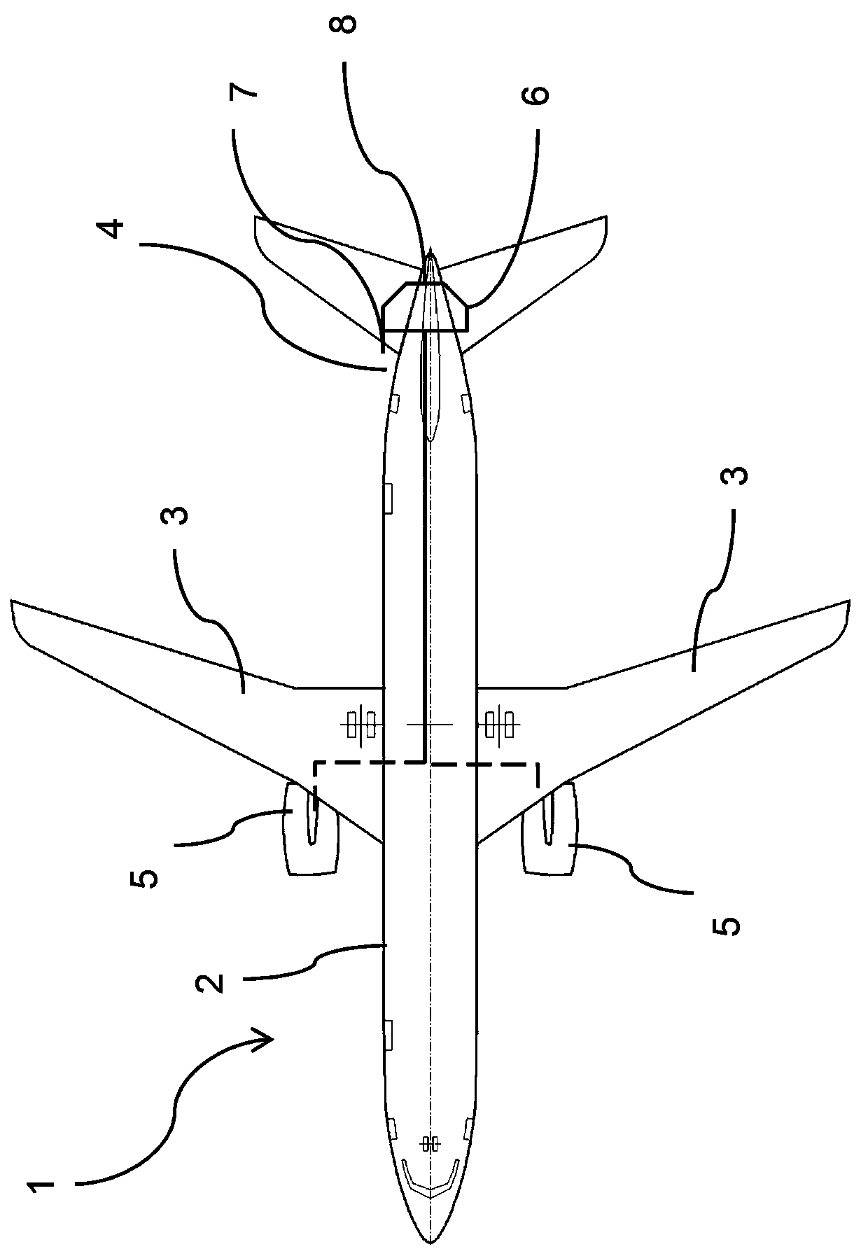
[0026] refer to figure 1 , shows aircraft 1 . The aircraft comprises a fuselage 2, wings 3, an empennage 4 located at the rear of the aircraft 1 and a propulsion system.

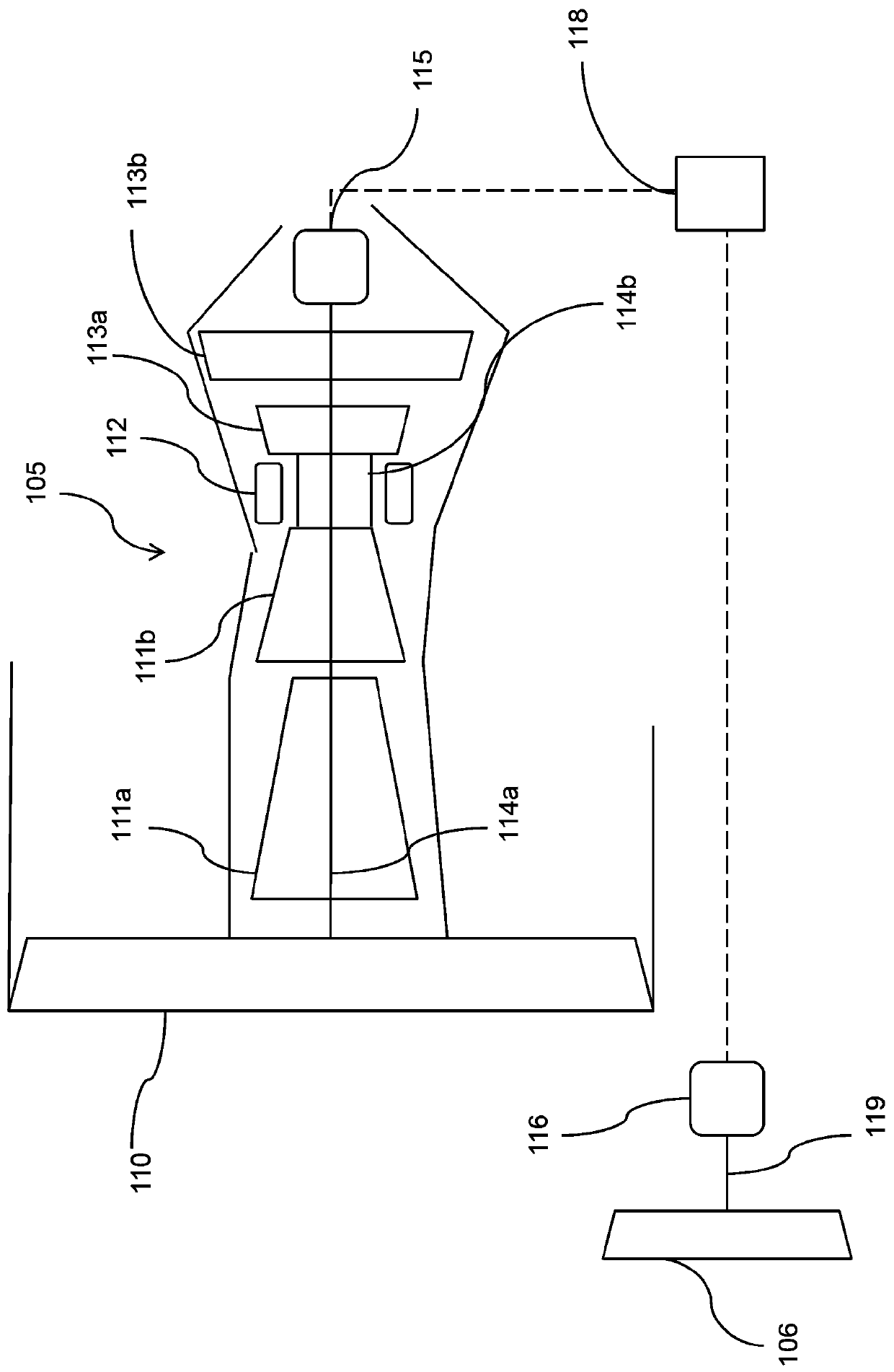
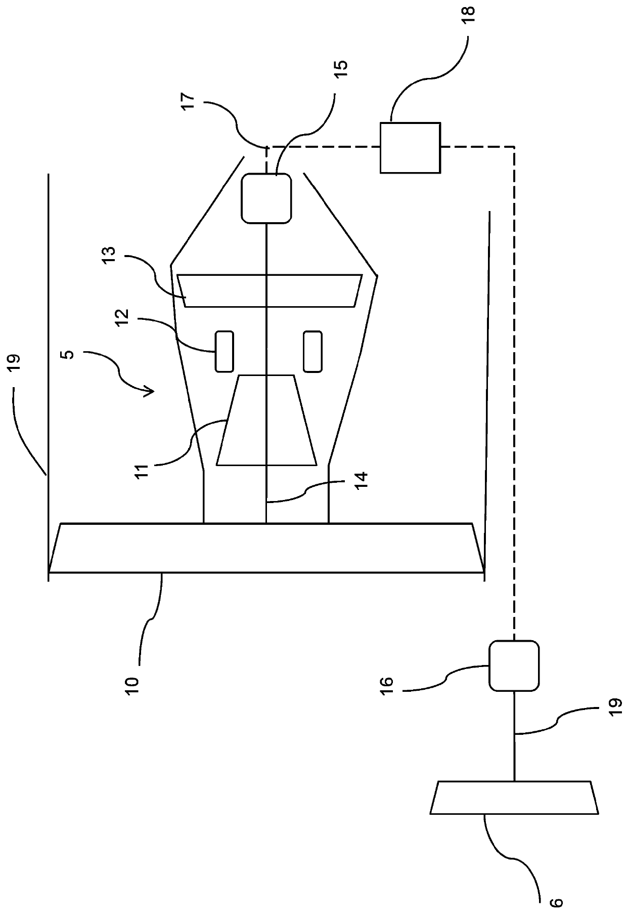
[0027] The propulsion system comprises a pair of gas turbine engines 5 , one on each wing 3 . Each gas turbine engine includes a mechanically driven fan 10 (such as figure 2 shown). The propulsion system also includes auxiliary propellers in the form of ducted Goldschmied propellers 6 located near the empennage 4 .

[0028] The Goldschmied propeller includes a ducted fan 6 having an inlet 7 configured to ingest boundary layer air. Boundary layer air is the air adjacent to the outer surfaces of the aircraft whose velocity in the aircraft frame of reference is less than 99% of the free stream velocity. Thus, in this embodiment, the inlet 7 is arranged close to the outer surface of the fuselage 2 in the vicinity of the empennage 4 , approximately at the longitudinal position of the leading edge of the hor...


PUM


Abstract

A hybrid aircraft propulsion system is disclosed. The system comprises a gas turbine engine (5) comprising a compressor (11), a combustor (12), one or more turbines (13), a shaft (14) coupled to one of the turbines (13), and a bypass fan (10) mechanically driven by the shaft (14). The system further comprises an electrical generator (15) mechanically coupled to the shaft (14), and an auxiliary propeller (6) mechanically coupled to an electric motor (16) and electrically coupled to the electric generator (15). At maximum power, the gas turbine engine (5) is configured to produce a turbine entrytemperature at maximum power between 1800 Kelvin and 2000 Kelvin, the engine comprises a fan bypass ratio of between 4:1 and 13:1, and the generator is configured to absorb between 10% and 60% of themechanical power generated by the turbine.

Description

technical field [0001] The present disclosure relates to propulsion systems for hybrid electric aircraft, and aircraft including such propulsion systems. Background technique [0002] Traditionally, aircraft are propelled by one or more propellers, such as fans or propellers driven by internal combustion engines such as gas turbine engines or piston engines. Traditionally, propellers are driven by direct drive shafts or reduction gearboxes. [0003] It has been proposed to replace or augment the power provided by mechanically driven propulsion fans by one or more electrically driven fans remote from the internal combustion engine. Such a system is known as a "hybrid propulsion system". In such a system, an electrically driven fan would be powered by a generator driven by an internal combustion engine. Advantages of such a system include the ability to provide additional control by providing thrusters at different locations, in addition to improved propulsion efficiency an...

Claims


Application Information

Patent Timeline
Patent Type & Authority Applications(China)
IPC IPC(8): B64D27/02F02K3/06F02C6/00F02C6/20
CPCB64D27/02F02K3/06F02C6/00F02C6/20B64D27/026B64D27/24B64D27/12B64D27/14B64C21/01F01D15/10F05D2220/76
Inventor D.P.斯科瑟恩
Owner ROLLS ROYCE PLC
Learn More