
Shearing pliers shearing waste automatic collecting device

A technology for automatic collection and waste, which is applied in metal processing, dust removal, cleaning methods and utensils, etc. It can solve the problems of flying randomly, not easy to control the flying direction of cut waste, waste, etc.

Inactive Publication Date: 2019-11-22
苏州赛至博电子科技有限公司
View PDF0 Cites 0 Cited by
  • Summary
  • Abstract
  • Description
  • Claims
  • Application Information

AI Technical Summary

Problems solved by technology

[0002] In electronics factories, small scissors are often used to cut the redundant legs of electronic components and other cutting waste. Generally, the cutting waste will be discarded directly after cutting, but for gold-plated or silver-plated component legs or other valuable The shearing waste needs to be collected and recycled again. In the prior art, manual recycling is used, but it is not easy to control the flying direction of the shearing waste during the shearing process. Flying around randomly will cause a large amount of shearing waste It cannot be collected in time, resulting in a lot of waste, which is not conducive to reducing production costs and is time-consuming and labor-intensive

Method used


Image

  • Shearing pliers shearing waste automatic collecting device
  • Shearing pliers shearing waste automatic collecting device
  • Shearing pliers shearing waste automatic collecting device

Examples


Embodiment 1

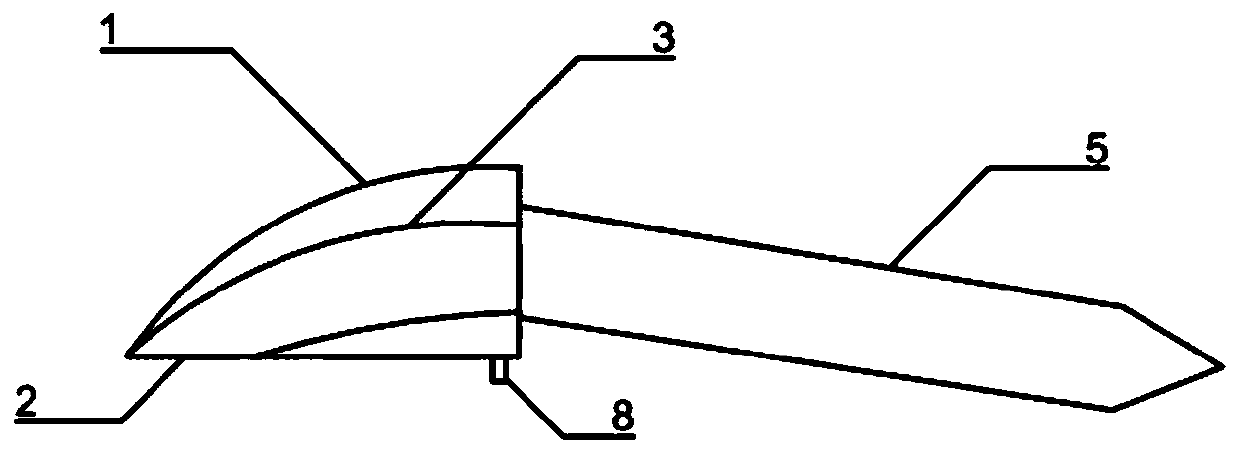
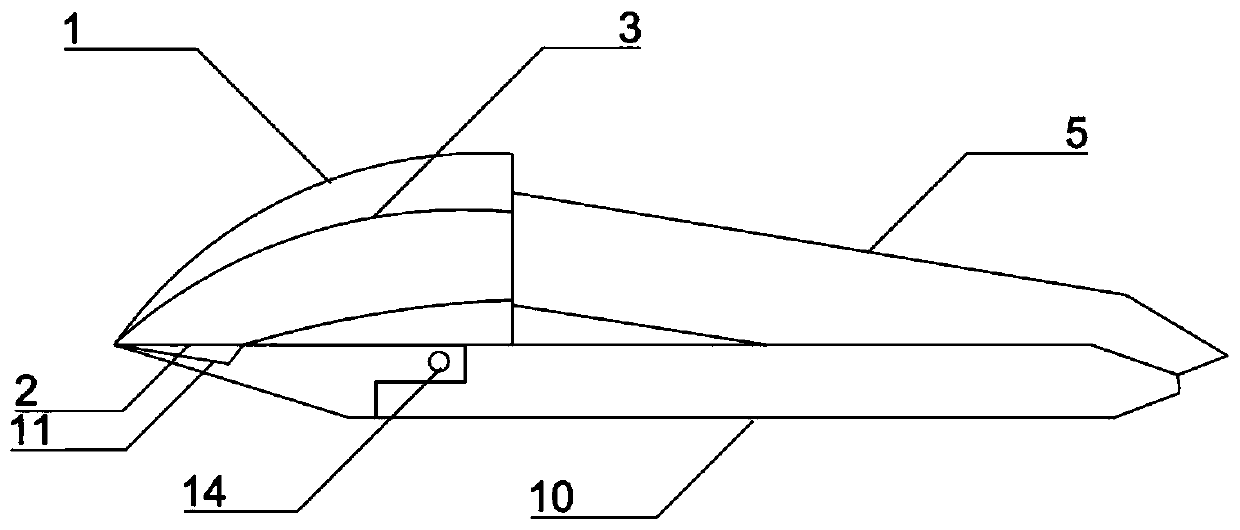
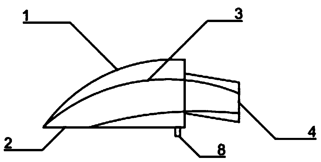
[0040]The present invention provides an automatic collection device for scissors cutting waste. Under the action of the shearing force of the scissors, the shearing waste flies in from the entrance 2 of the control member located directly above the jaws of the scissors 11 and passes through the direction. The upper arc-shaped channel 3 inside the control member flies, and after being reflected by the arc wall at the top of the upper arc-shaped channel, it flies out through the direction control member outlet 4 and enters the collection member 5 connected to the direction control member 1; wherein, the direction control member outlet 4 It is located on the right side of the direction control member and is arranged obliquely downward. The outer contour of the entrance of the direction control member matches the outer contour of the jaws 11 when the cutters are closed. The entrance of the direction control member is located at the front section of the bottom of the direction cont...

Embodiment 2

[0042] The present invention provides an automatic collection device for scissors cutting waste. Under the action of the shearing force of the scissors, the shearing waste flies in from the entrance 2 of the control member located directly above the jaws of the scissors 11 and passes through the direction. The upper arc-shaped channel 3 inside the control member flies, and after being reflected by the arc wall at the top of the upper arc-shaped channel, it flies out through the direction control member outlet 4 and enters the collection member 5 connected to the direction control member 1; wherein, the direction control member outlet 4 It is located on the right side of the direction control member and is arranged obliquely downward. The outer contour of the entrance of the direction control member matches the outer contour of the jaws 11 when the cutters are closed. The entrance of the direction control member is located at the front section of the bottom of the direction con...

Embodiment 3

[0044] The present invention provides an automatic collection device for cutting waste by scissors. Under the action of the shearing force of the scissors, the waste will fly in from the entrance 2 of the control member located directly above the jaws of the scissors 11 and pass through the direction. The upper arc-shaped channel 3 inside the control member flies, and after being reflected by the arc wall at the top of the upper arc-shaped channel, it flies out through the direction control member outlet 4 and enters the collection member 5 connected to the direction control member 1; wherein, the direction control member outlet 4 It is located on the right side of the direction control member and is arranged obliquely downward. The outer contour of the entrance of the direction control member matches the outer contour of the jaws 11 when the cutters are closed. The entrance of the direction control member is located at the front section of the bottom of the direction control ...


PUM


Abstract

The invention provides a shearing pliers shearing waste automatic collecting device. According to the device, the shearing waste flies from an inlet of a direction control component located right above the jaw of the shearing pliers under the action of shearing force of the shearing pliers and flies along an upper arc-shaped channel penetrating through the interior of the direction control component, and then enters a collecting component connected with the direction control component through the outlet of the direction control component after being reflected by the top arc wall of the upper arc-shaped channel; and the outlet of the direction control component is located on the right side face of the direction control component and is arranged obliquely downward. According to the shearingpliers shearing waste automatic collecting device, the flying direction of the shearing waste can be effectively controlled to enable the shearing waste to fly into a collecting mechanism accurately,so that the recycling efficiency is improved and the cost is reduced.

Description

technical field [0001] The invention relates to the field of parts processing waste collection, in particular to an automatic collection device for scissors cutting waste. Background technique [0002] In electronics factories, small scissors are often used to cut the redundant legs of electronic components and other cutting waste. Generally, the cutting waste will be discarded directly after cutting, but for gold-plated or silver-plated component legs or other valuable The shearing waste needs to be collected and recycled again. In the prior art, manual recycling is used, but it is not easy to control the flying direction of the shearing waste during the shearing process. Flying around randomly will cause a large amount of shearing waste Can not be collected in time, thereby causing a lot of waste, not conducive to reducing production costs and time-consuming and labor-intensive. [0003] To sum up, an automatic waste collection device matching small scissors needs to be d...

Claims


Application Information

Patent Timeline
Patent Type & Authority Applications(China)
IPC IPC(8): B26B17/00B08B15/04
CPCB08B15/04B26B17/00
Inventor 张波
Owner 苏州赛至博电子科技有限公司
Learn More