A fixed installation structure for electric equipment

A technology for installation structure and power equipment, which is applied in the direction of metal processing equipment, other manufacturing equipment/tools, driving devices, etc. It can solve the problems of difficult disassembly and assembly of cylindrical rollers, achieve convenient disassembly and assembly, convenient replacement, and improve work efficiency Effect

Active Publication Date: 2021-03-19
ANHUI TELECOMM ENG
View PDF7 Cites 0 Cited by
  • Summary
  • Abstract
  • Description
  • Claims
  • Application Information

AI Technical Summary

Problems solved by technology

[0009] The purpose of the present invention is to overcome the deficiencies of the prior art, adapt to the actual needs, and provide a fixed installation structure for electric equipment to solve the problem that the existing cylindrical roller is not easy to disassemble

Method used


Image

  • A fixed installation structure for electric equipment
  • A fixed installation structure for electric equipment
  • A fixed installation structure for electric equipment

Examples


Embodiment Construction

[0045] Attached below Figure 1-10 The present invention is further described with examples:

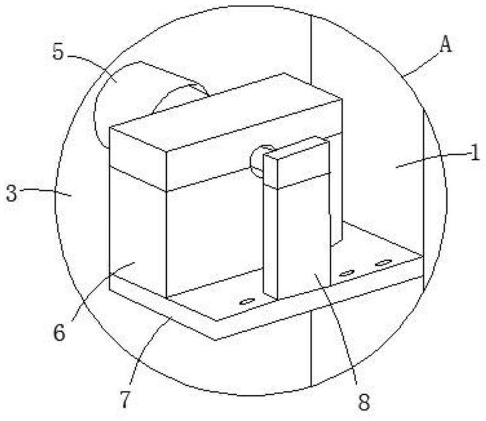
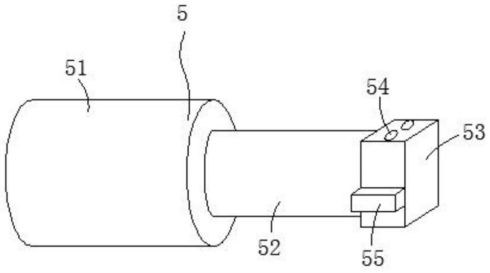
[0046]A fixed installation structure for electric equipment, including a roller 3, the rear end of the roller 3 is connected to a support frame 1 through a driving device, the front end of the roller 3 is provided with a connecting piece 5, and the support frame 1 is arranged on a base 4, The support frame 1 is located directly above the roller 3 and is provided with a punching device 2, and the base 4 is provided with a processing device 9; the connecting piece 5 includes a connecting column 51, which is connected to the roller 3, and the connecting column 51 is far away from the roller One end of the cylinder 3 is provided with one end of a support column 52, and the other end of the support column 52 is fixedly provided with a connection block 53, and the top end of the connection block 53 is provided with a clamping hole 54, and the side wall of the connection block 53 is fixedly...


PUM


Abstract

The invention relates to a fixing and mounting structure for a power system. The structure comprises a connecting column, wherein the connecting column is connected to a roller, the end, far away fromthe roller, of the connecting column is provided with one end of a supporting column, a connecting block is fixedly arranged at the other end of the supporting column, a clamping hole is formed in the top end of the connecting block, and a positioning block is fixedly arranged on the side wall of the connecting block. In the structure, the roller is detachably installed, the damaged roller can beconveniently replaced, punching on cylindrical filter screens with various bore diameters can be realized by replacing rollers with different diameters, meanwhile, the punching and deburring procedures can be carried out at the same time through the structure, so that the effects of saving time and saving labor are achieved.

Description

technical field [0001] The present invention relates to the technical field of electrical equipment, in particular to a fixed installation structure for electrical equipment. Background technique [0002] Power equipment (power system) is a power production and consumption system composed of power generation, transmission, substation, distribution and power consumption. It converts primary energy in nature into electricity through power generation devices, and then supplies electricity to users through power transmission, transformation and distribution. It mainly includes two categories: power generation equipment and power supply equipment. The power generation equipment is mainly power station boilers, steam turbines, gas turbines, hydraulic turbines, generators, point motors, transformers, etc. The power supply equipment is mainly transmission lines and transformers of various voltage levels. , contactors, etc. [0003] The patent with the announcement number of CN2064...

Claims


Application Information

Patent Timeline
Patent Type & Authority Patents(China)
IPC IPC(8): B23P23/04B23Q7/05B23Q5/04
CPCB23P23/04B23Q5/04B23Q7/05
Inventor 夏波另大兵何泽清张鹏
Owner ANHUI TELECOMM ENG
Why Eureka
Try Eureka