
Motor assembly, exhaust assembly and exhaust method of dust collector, and dust collector

A technology for motor components and vacuum cleaners, which is applied in the installation of vacuum cleaners, exhaust diffusers, motor fan components, etc. It can solve the problems of affecting the heat dissipation of motors, increasing the consumption of consumables and processing costs, and the noise of vacuum cleaners, etc., to improve heat dissipation performance , Reduce the consumption of consumables, improve the effect of heat dissipation area

Pending Publication Date: 2019-11-22
PUPPY ELECTRONICS APPLIANCES INTERNET TECH (BEIJING) CO LTD
View PDF9 Cites 0 Cited by
  • Summary
  • Abstract
  • Description
  • Claims
  • Application Information

AI Technical Summary

Problems solved by technology

[0005] In view of the above analysis, the present application aims to provide a vacuum cleaner motor assembly, exhaust assembly, exhaust method and vacuum cleaner, which solves the problem of increasing the consumption of consumables and processing costs caused by the sealing of the motor as a whole in the prior art, affecting the heat dissipation of the motor, and The problem of loud noise during the exhaust process of the vacuum cleaner

Method used


Image

  • Motor assembly, exhaust assembly and exhaust method of dust collector, and dust collector
  • Motor assembly, exhaust assembly and exhaust method of dust collector, and dust collector
  • Motor assembly, exhaust assembly and exhaust method of dust collector, and dust collector

Examples


Embodiment 1

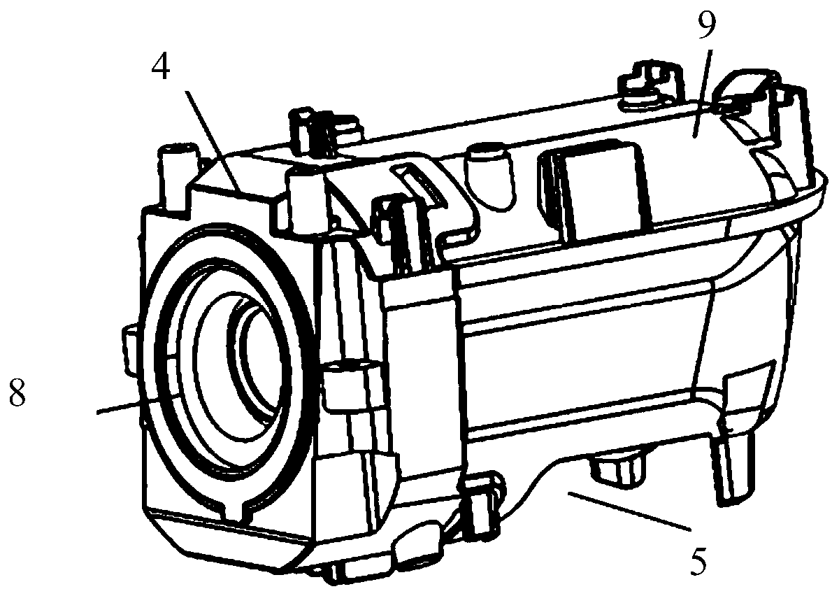
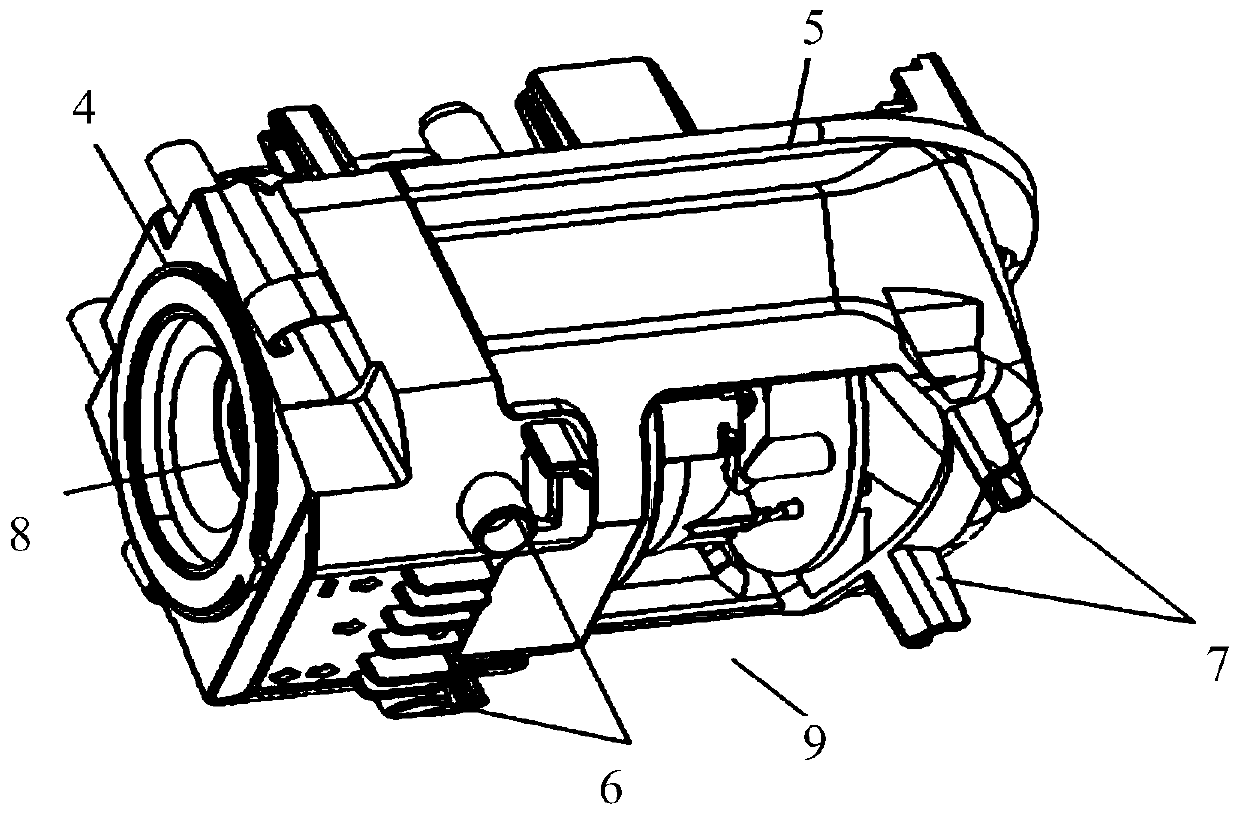
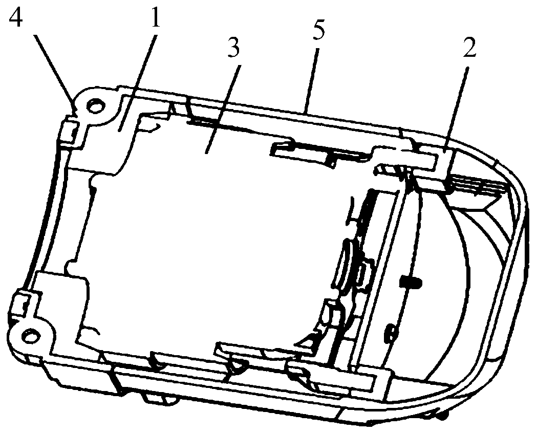
[0053] This embodiment provides a motor assembly, see Figure 1 to Figure 5, including a motor housing, a motor body 3 and a shock absorber assembly disposed in the motor housing, the shock absorber assembly is a split structure, including a shock absorber 1 at the air inlet end and a shock absorber 2 at the air outlet end. Wherein, the shock absorber 1 at the air inlet end is arranged between the air inlet end of the motor housing and the air inlet end of the motor body 3, the shock absorber 1 at the air inlet end is set on the outer wall of the air inlet end of the motor body 3, and the air inlet end is cushioned. The air inlet surface and the side surface of the vibration part 1 are respectively in contact with the inner wall of the motor housing, and the shock absorbing part 2 at the air outlet end is arranged between the air outlet end of the motor housing and the air outlet end of the motor body 3, and the air outlet end is cushioned Part 2 is sleeved on the outer wall o...

Embodiment 2

[0063] This embodiment provides a vacuum cleaner exhaust assembly, see Figure 6 , including the motor assembly provided in the first embodiment, the motor assembly is arranged above the handle 10 of the vacuum cleaner.

[0064] Compared with the prior art, the beneficial effects of the exhaust assembly of the vacuum cleaner provided in this embodiment are basically the same as those of the motor assembly provided in Embodiment 1, and will not be repeated here.

[0065] It can be understood that, in order to realize the exhaust function of the above-mentioned exhaust assembly, it may also include a main exhaust passage 11 , a main exhaust hole 12 , an auxiliary exhaust passage 13 and an auxiliary exhaust hole 14 . Wherein, the main exhaust duct 11 is arranged in the handle, and the main exhaust hole 12 is arranged at the bottom of the handle. One end of the main exhaust duct 11 is communicated with the air outlet of the motor housing, and the other end is communicated with the...

Embodiment 3

[0076] This embodiment provides a vacuum cleaner, see Figure 7 , along the intake direction of the vacuum cleaner, sequentially include the front-end unit and the exhaust assembly provided by the second embodiment.

[0077] Compared with the prior art, the beneficial effects of the vacuum cleaner provided by this embodiment are basically the same as those of the exhaust assembly provided by Embodiment 2, and will not be repeated here.

[0078] It can be understood that the above-mentioned vacuum cleaner can also include a hanger for the vacuum cleaner, see Figure 8 to Figure 9 , the vacuum cleaner hanger includes a body and a connector. The connector is set on the body and protrudes from the body to form a hanging structure. The base of the main unit of the vacuum cleaner is hung on the connector. The groove realizes the connection between the base and the hanger of the vacuum cleaner by placing the connecting piece in the connecting groove. The above-mentioned vacuum clea...


PUM


Abstract

The application discloses a motor assembly, an exhaust assembly, an exhaust method of a dust collector and the dust collector and belongs to the technical field of cleaning equipment, and the problemsthat the use amount and the machining cost are increased due to the fact that a sealing part is used for wrapping a motor, the heat dissipation of the motor is influenced, and the noise of the dust collector in the exhaust process is large. The motor assembly in the application comprises a motor housing, a motor body and a cushioning assembly; an air inlet end cushioning member is arranged between an air inlet end of the motor housing and an air inlet end of the motor body, and an air outlet end cushioning member is arranged between an air outlet end of the motor housing and an air outlet endof the motor body. The exhaust assembly in the application comprises a motor assembly, a main exhaust passage, a main exhaust hole, an auxiliary exhaust passage and an auxiliary exhaust hole; the main exhaust passage is arranged in a handle, and the auxiliary exhaust passage is arranged between an air outlet of the motor housing and an upper housing of the dust collector. The motor assembly, theexhaust assembly, the exhaust method of the dust collector and the dust collector in the application can be used for cleaning a working surface.

Description

technical field [0001] The present application relates to a cleaning device, in particular to a motor assembly of a vacuum cleaner, an exhaust assembly, an exhaust method and the vacuum cleaner. Background technique [0002] In the existing vacuum cleaners, in order to reduce the vibration generated by the motor during operation, a sealing material is usually arranged between the motor and the motor housing so that it wraps around the outside of the motor. [0003] However, the position where the motor vibrates is limited to a few positions, and it is not necessary to wrap the motor as a whole inside the seal. This method will not only increase the consumption of consumables and processing costs, but also seriously affect the heat dissipation of the motor. [0004] In addition, the existing vacuum cleaner only has a single exhaust channel, which causes the gas to flow too fast when passing through the exhaust channel, which makes the vacuum cleaner generate a lot of noise du...

Claims


Application Information

Patent Timeline
Patent Type & Authority Applications(China)
IPC IPC(8): A47L5/12A47L9/00A47L9/22
CPCA47L5/12A47L9/0081A47L9/22
Inventor 檀冲徐龙闻丹丹秦阳邵琦峰马云孙书进谢中山
Owner PUPPY ELECTRONICS APPLIANCES INTERNET TECH (BEIJING) CO LTD
Learn More