
Non-sensing payment system and method for toll station

A payment system and toll station technology, applied in the field of non-inductive payment, can solve the problems of time delay, troublesome payment at gas stations, poor service quality of non-inductive payment, etc., and achieve the effect of improving the process.

Inactive Publication Date: 2019-11-19
NANJING SILICON INTELLIGENCE TECH CO LTD
View PDF6 Cites 2 Cited by
  • Summary
  • Abstract
  • Description
  • Claims
  • Application Information

AI Technical Summary

Problems solved by technology

[0004] The patent with the publication number CN109767202A - a non-inductive payment method and equipment based on license plate recognition, wherein the method includes: when the vehicle drives to a preset area, scan the license plate of the vehicle through the camera to obtain the license plate information of the vehicle; combine the license plate information with the database Match the account information in the account to refuel, refuel or charge the vehicle; perform transaction payment according to the transaction data and account information of the refueling machine, refueling machine or charging machine corresponding to the preset area; solve the problem of payment troubles at refueling stations Technical issues; in this patent, the payment process is only confirmed once. Once an unexpected situation occurs during the confirmation, it will delay a lot of time. From the perspective of the driver, if there is no reasonable reminder and reassurance, it will be considered indifferent The paid service quality is poor, and it is easy to cause conflicts between the driver and the charging party

Method used


Image

  • Non-sensing payment system and method for toll station
  • Non-sensing payment system and method for toll station

Examples


Embodiment Construction

[0030] The present invention will be further described in detail below with reference to the accompanying drawings.

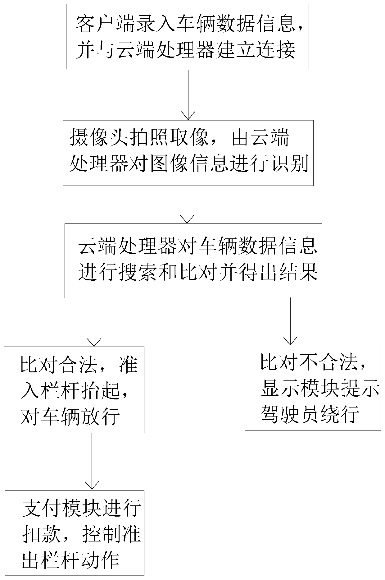
[0031] A sensorless payment system for toll booths, comprising a correspondingly connected client, a cloud processor, a camera, a system database, a pass interception module, a display module and a payment module;

[0032] The client is a mobile phone or a computer, and the mobile phone or computer establishes a legal connection with the cloud processor, and the client is used to input vehicle information in the entire non-inductive payment system, so that the vehicle information can be stored in the non-inductive payment system of the present invention. The client can make the driver side or the toll station side. When it is the toll station side, it can assist and teach the driver to use the non-inductive payment system to pay at the toll station;

[0033] The cloud processor is used to process images, data and issue control commands. The cloud processor is t...


PUM


Abstract

The invention relates to the field of non-sensing payment, discloses a non-sensing payment system and method for a toll station, and solves the problem of poor payment process service quality caused by simultaneous legal connection confirmation and deduction confirmation. According to the key points of the technical scheme, the system comprises a client, a cloud processor, a camera, a system database, a passing interception module, a display module and a payment module; the cloud processor is used for processing images and data and sending control instructions; the camera is used for shootingtarget vehicles; the system database is used for storing vehicle data information; the passing interception module comprises an entrance railing and an exit railing, and is used for controlling the passing of the vehicles; the display module comprises a display screen, and is used for displaying reminding information to vehicle drivers on non-sensing payment lanes; and the payment module is used for calculating and deducting fees. The legal confirmation and the deduction confirmation are separated; the vehicles are guided in the whole process; the passing payment process is humanized; and theservice quality is high.

Description

technical field [0001] The present invention relates to the field of non-inductive payment, and more particularly, to a non-inductive payment system and method for toll booths. Background technique [0002] Non-inductive payment, that is, with the help of a unique feature of the item, bind the relevant payment tool, and then identify the feature through biometrics or image scanning, so as to complete the payment method. [0003] At present, some toll stations also adopt the method of non-inductive payment for charging. Generally, the legal confirmation and deduction confirmation are carried out at the same time only after one confirmation when charging. If the deduction is unsuccessful due to insufficient balance of the driver's payment tool In this case, the non-inductive payment will not be successful, and the vehicle will be directly intercepted and can only be detoured. From the driver's point of view, the vehicle has been legally connected to the non-inductive payment s...

Claims


Application Information

Patent Timeline
IPC IPC(8): G07B15/02G07B15/06G06K9/00G06K9/62
CPCG07B15/02G07B15/06G06V20/584G06F18/22
Inventor 司马华鹏
Owner NANJING SILICON INTELLIGENCE TECH CO LTD
Learn More