Morphology Prediction Method of Metal Cutting Tool Nose Dead Zone Considering Metal Slip

A technology of metal cutting and metal sliding, applied in geometric CAD and other directions

Active Publication Date: 2022-03-01
NORTHWESTERN POLYTECHNICAL UNIV
View PDF5 Cites 0 Cited by
  • Summary
  • Abstract
  • Description
  • Claims
  • Application Information

AI Technical Summary

Problems solved by technology

[0007] In order to overcome the problem that the existing methods need to artificially select part of the content when modeling the dead zone of the tool tip, the present invention provides a method for completely theoretically calculating the shape of the dead zone using the metal slip line theory

Method used


Image

  • Morphology Prediction Method of Metal Cutting Tool Nose Dead Zone Considering Metal Slip
  • Morphology Prediction Method of Metal Cutting Tool Nose Dead Zone Considering Metal Slip
  • Morphology Prediction Method of Metal Cutting Tool Nose Dead Zone Considering Metal Slip

Examples


Embodiment 1

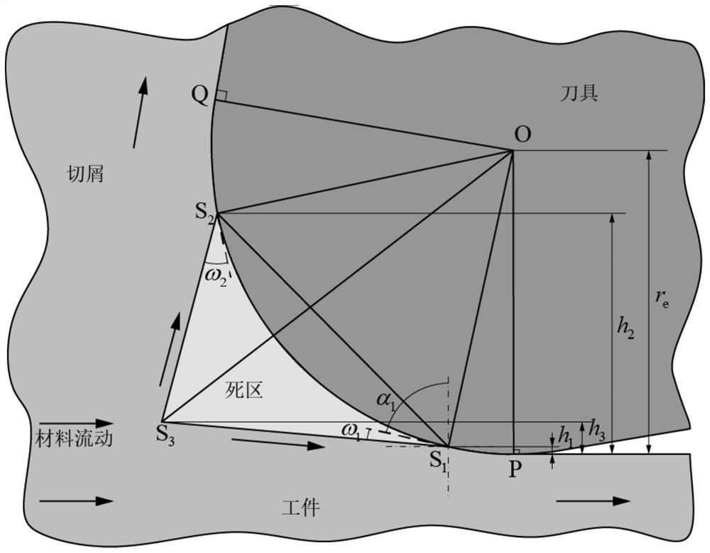
[0097] The finite element simulation is set to a two-dimensional right-angle cutting simulation model of aluminum alloy 7050-T7451, and the tool is set to the radius r of the blunt circle of the tool tip e = 0.02 mm, rake angle α = 5 degrees. The friction coefficient between the blunt circle of the tool nose and the rake face is determined by the cutting data published in the right-angle cutting parameter library. The modeling method of the model refers to the finite element modeling method disclosed in the literature "X.Jin, Y.Altintas, Prediction of micro-milling forces with finite element method, Journal of Materials Processing Technology 212(3)(2012)542-552." .

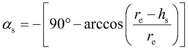
[0098] Step 1. Set the distance from an unknown point on the blunt circle of the knife tip to the lowest point of the blunt circle as h s . The rake angle α at the unknown point on the blunt circle of the tool tip s Expressed as:

[0099]

[0100] The shear angle φ s Expressed as:

[0101] φ s =45°-(β ...


PUM


Abstract

The invention relates to a method for completely theoretically calculating the shape of the dead zone by using the metal slip line theory. Firstly, it is necessary to determine the radius of the blunt circle of the tool tip used by the tool through measurement. Then it is necessary to calculate the rake angle and friction angle of each position on the blunt circle of the tool tip, and then obtain the shear angle at each position, that is, the shear direction of the metal. Then use the friction angle to obtain the friction coefficient of each position, and then solve the angle between the metal slip line and the plastic boundary, that is, the angle between the boundary line of the dead zone and the blunt circle of the tool tip. Let the metal shearing direction be collinear with the boundary line of the dead zone, then the vertex S of the dead zone on the blunt circle of the knife tip can be solved 1 and S 2 s position. Judgment Vertex S 1 and S 2 After existence, use the vertex S 1 and S 2 and the angle between the boundary line of the dead zone and the blunt circle of the tool tip at these two points, the vertex S is obtained by deriving the geometric relationship 3 The position of the tool tip can completely determine the shape of the dead zone of the tool tip. The present invention can predict the complete shape of the dead zone of the tool tip through complete theoretical calculation without any artificially given factors.

Description

technical field [0001] The invention relates to a method for predicting metal flow at the tip of a cutting tool, in particular to a method for predicting the shape of a dead zone in consideration of the blunt roundness of the tip of the tool to form a dead zone formed by metal stagnation at the tip of the tool. Background technique [0002] In modeling metal cutting, it is common to consider the tip of a tool to be perfectly sharp. However, in practice, there will always be a blunt circle at the tip of the tool, especially for micro-cutting processes or when using passivated tools, the cutting amount of the cutter tooth is equivalent to the radius of the blunt circle of the tool tip, and the influence of the blunt circle cannot be ignored. At this time, the metal will form a stagnation near the blade, forming a dead zone. The flow velocity of the metal inside and outside the dead zone is different, that is, there is a flow velocity discontinuity in the normal direction of t...

Claims


Application Information

Patent Timeline
Patent Type & Authority Patents(China)
IPC IPC(8): G06F30/17
Inventor 万敏温丹阳张卫红杨昀
Owner NORTHWESTERN POLYTECHNICAL UNIV
Why Eureka
Try Eureka