


Quick Research
Generate reliable direction feasibility study reports for your R&D in just a few steps.

Technical Q&A
Discover and master advanced knowledge NOW. Basics, ideas, possibilities, all at once.

Find Solutions
As an expert in R&D theories, this can generate solutions to your technical problems instantly.

Evaluate Feasibility
Analyze your overall solution with one click, know your potential R&D risks in advance.

Monitor Landscape
Get weekly tech updates, stay abreast of the latest tech innovations and key insights.
Solar evacuated tube
A technology of vacuum heat collecting tube and solar energy, which is applied in the field of solar energy, can solve the problems of thermal expansion and elongation, easy to burst, small diameter, easy to foul and block, etc., and achieve the effect of solving the expansion and contraction effect and improving the expansion and contraction rate
- Summary
- Abstract
- Description
- Claims
- Application Information
AI Technical Summary
Problems solved by technology
Method used
Image


Examples
Embodiment 1
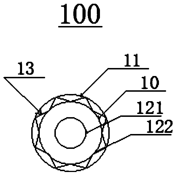
[0055] figure 1 It is a cross-sectional view of the solar vacuum heat collecting tube 100 provided in Embodiment 1 of the present invention.
[0056] Please refer to figure 1 , a solar vacuum heat collecting tube 100, comprising a glass inner tube 10 and a glass outer tube 11, the glass outer tube 11 is sleeved on the glass inner tube 10;
[0057] The glass outer tube 11 and / or the glass inner tube 10 are provided with concavo-convex corrugated grooves 12 .
[0058] It is worth noting that the solar vacuum heat collection tube 100 is provided with concave-convex corrugated grooves 12 on the glass outer tube 11 and / or glass inner tube 10, so that when the glass inner tube 10 absorbs sunlight and converts heat energy, the concave-convex corrugated grooves 12 It plays a stretching role when thermal expansion elongates, so as to avoid thermal expansion that may easily cause the solar vacuum heat collecting tube 100 to burst. The structure is reasonable in design and strong in pr...
Embodiment 2
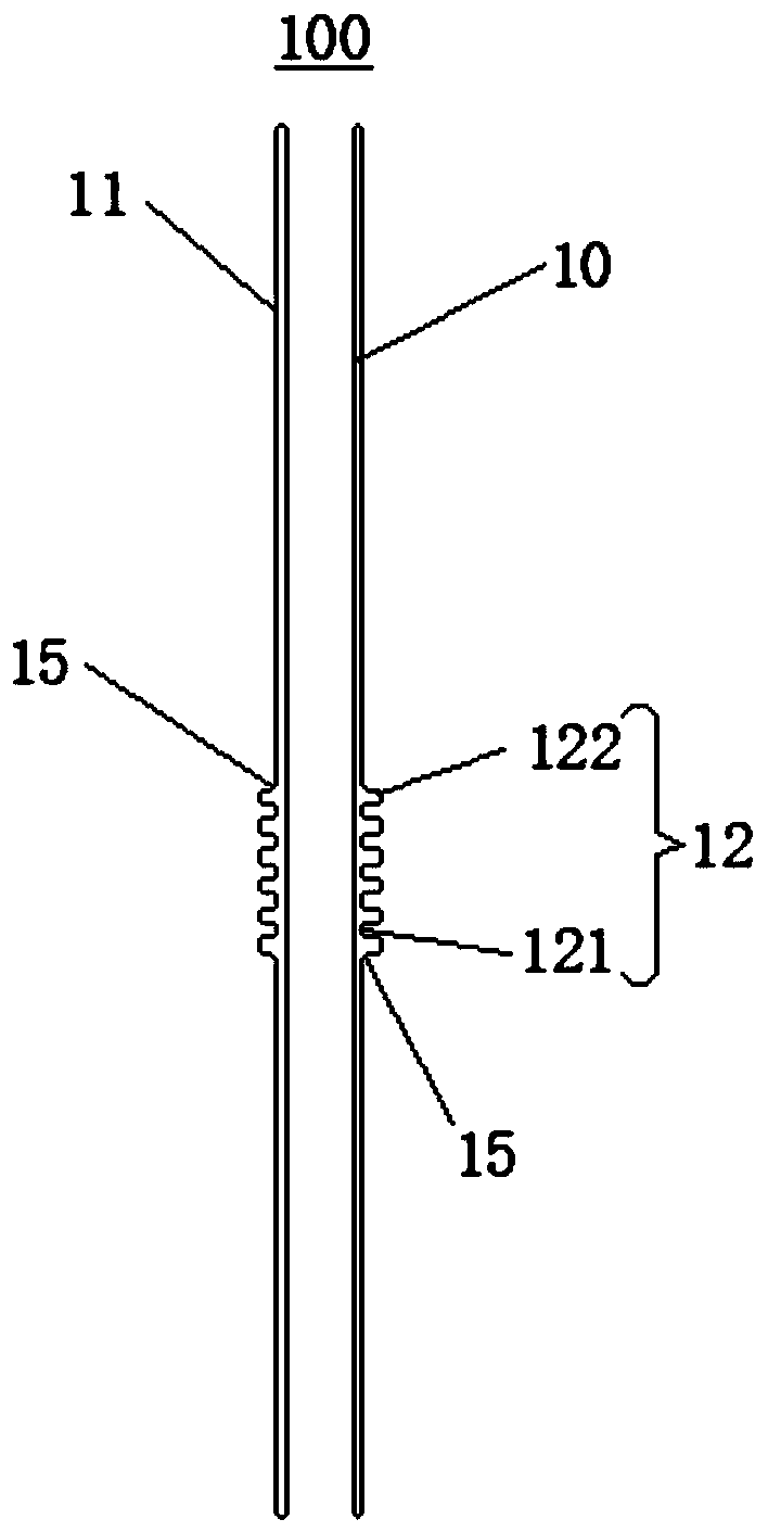
[0073] image 3 A cross-sectional view of the solar vacuum heat collecting tube 100 provided by Embodiment 2 of the present invention.
[0074] Figure 4 A cross-sectional view of the solar vacuum heat collecting tube 100 provided for Embodiment 2 of the present invention.
[0075] Please refer to image 3 and Figure 4 , In Embodiment 2, the concave-convex corrugated groove 12 is provided on the glass outer tube 11 . The joint between the glass outer tube 11 and the concave-convex corrugated groove 12 is the second connecting section 15, and the second connecting section 15 is arc-shaped.
[0076] It is worth noting that the connection between the glass outer tube 11 and the concave-convex corrugated groove 12 is set as an arc, which can avoid the sharp connection between the concave-convex corrugated groove 12 and the glass outer tube 11. When the temperature rises, the thermal expansion coefficient elongates A buffer effect is played to prevent the solar vacuum heat co...
Embodiment 3
[0081] Figure 5 A cross-sectional view of the solar vacuum heat collecting tube 100 provided in Embodiment 3 of the present invention.
[0082] Figure 6 A cross-sectional view of the solar vacuum heat collecting tube 100 provided for Embodiment 3 of the present invention.
[0083] Please refer to Figure 5 and Figure 6 , In Embodiment 2, the concave-convex corrugated groove 12 is arranged on the glass outer tube 11 and the glass inner tube 10 .
[0084] The concave-convex corrugated groove 12 on the glass inner tube 10 is located inside the cross section of the glass inner tube 10;
[0085] The concave-convex corrugated groove 12 on the glass outer tube 11 is located outside the cross section of the glass outer tube 11 .
[0086] It is worth noting that arranging the concave-convex corrugated groove 12 inside the cross section of the glass inner tube 10 can ensure a constant distance between the glass inner tube 10 and the glass outer tube 11, and at the same time prev...
PUM
| Property | Measurement | Unit |
|---|---|---|
| Diameter | aaaaa | aaaaa |
| Diameter | aaaaa | aaaaa |
| Thickness | aaaaa | aaaaa |
Abstract
Description
Claims
Application Information
 - R&D Engineer
- R&D Manager
- IP Professional
- Industry Leading Data Capabilities
- Powerful AI technology
- Patent DNA Extraction
Browse by: Latest US Patents, China's latest patents, Technical Efficacy Thesaurus, Application Domain, Technology Topic, Popular Technical Reports.
© 2024 PatSnap. All rights reserved.Legal|Privacy policy|Modern Slavery Act Transparency Statement|Sitemap|About US| Contact US: help@patsnap.com