A co that utilizes lng cold energy and exploits hydrate 2 Capture device and capture method thereof

A hydrate and CO2 technology, applied in the container discharge method, container filling method, gas/liquid distribution and storage, etc., can solve the problems of inability to achieve storage, inability to efficiently utilize LNG cold energy, inability to efficiently utilize BOG, etc., to achieve Efficient utilization and the effect of improving exergy efficiency

Active Publication Date: 2021-02-05
CHINA PETROLEUM & CHEM CORP +1
View PDF6 Cites 0 Cited by
  • Summary
  • Abstract
  • Description
  • Claims
  • Application Information

AI Technical Summary

Problems solved by technology

[0006] The purpose of the present invention is to provide a CO 2 The capture device and its capture method solve the problem of injecting replacement gas into the hydrate layer during the process of hydrate replacement mining in the prior art, and the replacement gas enters the hydrate cage to replace the CH in the hydrate cage. 4 (methane), so as to achieve the purpose of mining. In this process, the existing technology cannot efficiently utilize the cold energy of LNG (liquefied natural gas), and at the same time, it cannot efficiently utilize BOG (boil-off gas), and in the process of CO 2 Good storage cannot be achieved after liquefaction

Method used


Image

  • A co that utilizes lng cold energy and exploits hydrate  <sub>2</sub> Capture device and capture method thereof
  • A co that utilizes lng cold energy and exploits hydrate  <sub>2</sub> Capture device and capture method thereof

Examples


Embodiment 1

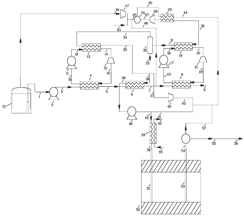
[0035] Such as figure 1 As shown, the figure schematically shows the LNG (liquefied natural gas) cold energy utilization and CO hydrate extraction 2 The capture device includes LNG vaporization system, BOG (boil-off gas) treatment system and CO 2 recycling system.

[0036] In the embodiment of the present application, the LNG vaporization system includes a liquid-phase zone heating subsystem, a gas-liquid two-phase zone heating subsystem, and a gas-phase zone heating subsystem connected in sequence, wherein the output end of the gas-phase zone heating subsystem outputs For natural gas products, the gas-liquid two-phase zone heating subsystem is connected to the BOG processing system, and is used to transport the low-temperature natural gas obtained after the gas-liquid two-phase zone heating subsystem is heated and vaporized to the BOG processing system to balance the BOG processing System material supply.

[0037] The CO 2 The vaporization pressurization output system is ...

Embodiment 2

[0058] This embodiment is basically the same as Embodiment 1. For the sake of brevity, in the description process of this embodiment, the same technical features as Embodiment 1 will not be described, and only the differences between this embodiment and Embodiment 1 will be described:

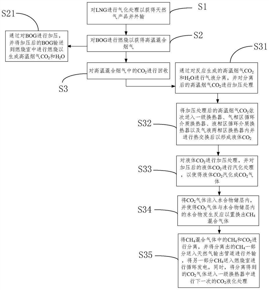
[0059] Such as figure 2 As shown, according to the second aspect of the present application, a CO 2 A capture method comprising the steps of:

[0060] Step S1, performing gasification treatment on LNG to obtain natural gas products and exporting them.

[0061] Step S2, burning the BOG to obtain high-temperature mixed flue gas.

[0062] Step S3, the CO in the high temperature mixed flue gas 2 to recycle.

[0063] In a preferred embodiment, in step S1, the method further includes: making LNG sequentially pass through the liquid-phase zone heating subsystem, the gas-liquid two-phase zone heating subsystem and the gas-phase zone heating subsystem to perform heat exchange to obtain all natural g...


PUM


Abstract

The invention relates to the technical field of oil-gas storage and transportation engineering, and discloses a CO2 capturing device and capturing method achieving LNG cold energy utilization and hydrate exploitation. The device comprises an LNG vaporization system, a BOG treatment system and a CO2 recovery system. The LNG vaporization system comprises a liquid phase area temperature increase subsystem, a gas-liquid two-phase area temperature increase subsystem and a gas phase area temperature increase subsystem which are connected in sequence. The gas-liquid two-phase area temperature increase subsystem is connected with the BOG treatment system. A CO2 vaporization pressurization output system is connected with the BOG treatment system and the CO2 recovery system, so that flue gas CO2 generated by the BOG treatment system is injected into a hydration reservoir so as to replace CH4 gas and part of flue gas CO2 gas, and the CH4 gas and the flue gas CO2 gas are conveyed to the CO2 recovery system to be subjected to further recovery treatment. The CO2 recovery system is connected with the liquid phase area temperature increase subsystem and the gas-liquid two-phase area temperature increase subsystem. The CO2 capturing device achieving LNG cold energy utilization and hydrate exploitation has the advantages that the LNG cold energy utilization rate is high and CO2 is effectively captured.

Description

technical field [0001] The invention relates to the technical field of oil and gas storage and transportation engineering, in particular to a CO 2 Capture device and capture method thereof. Background technique [0002] LNG is a low-temperature liquid mixture at -162°C under normal pressure. When gasifying each ton of LNG, it can generate about 240kWh of cold energy. Reasonable use of this part of cold energy can produce considerable economic benefits. Among them, cold energy can be used in power generation, low-temperature cold storage and ice storage and other fields. The temperature of LNG rises from -162°C to 10°C during the release of cold energy, and the temperature span is large. Therefore, if a single-stage Rankine cycle power generation system is established, the heat transfer temperature difference of the Rankine cycle power generation system is large, which is likely to cause cold. The loss of exergy is large, and it is difficult to improve the utilization effic...

Claims


Application Information

Patent Timeline
Patent Type & Authority Patents(China)
IPC IPC(8): F17C7/04F17C13/00F17D3/01
CPCF17C7/04F17C13/00F17D3/01
Inventor 薛倩王晓霖李遵照刘名瑞李雪
Owner CHINA PETROLEUM & CHEM CORP
Why Eureka
Try Eureka