Gas co-generation technology optimizing system

A technology of combined heat and power supply and process optimization, applied in the directions of preheating, feed water heater, combined combustion mitigation, etc., can solve the problems of low efficiency, unsuitable for regional collective heating and power supply, and achieve mature application technology and improve equipment. Utilization, applicability and popularization effect

Pending Publication Date: 2017-09-15
SOUTH CHINA UNIV OF TECH +1
View PDF6 Cites 3 Cited by
  • Summary
  • Abstract
  • Description
  • Claims
  • Application Information

AI Technical Summary

Problems solved by technology

The entire process of this combined heat and power system is very simple and practical, but under the condition of multiple modules for power transmission and heat transmission, it can only supply individual users, the overall efficiency is low, and it is not suitable for regional collective heating, Status of power supply

Method used


Image

  • Gas co-generation technology optimizing system

Examples


Embodiment Construction

[0028] In order to better understand the present invention, the present invention will be further described below in conjunction with the examples and accompanying drawings, but the embodiments of the present invention are not limited thereto.

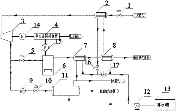
[0029] Such as figure 1 As shown, a gas-fired combined heat and power process optimization system includes a power generation grid-connected system and a heating system;

[0030] The power generation and grid connection system includes first control valves 1, 1 connected to the gas pipeline network in sequence through pipelines # The heat exchanger 2, the expander 3, the gas after the expander 3 is divided into two paths, one path is connected to the first pressure regulating valve 5, the micro-combustion engine 6, and the second generator 15 in sequence, and the other path is connected to the heating equipment in sequence 9. The second pressure regulating valve 10, the flow meter, and the original industrial boiler 11. The first pres...


PUM


Abstract

The invention discloses a gas co-generation technology optimizing system. The gas co-generation technology optimizing system comprises a power generation grid-connected system and a heat supply system. The power generation grid-connected system comprises a first control valve, a 1# heat exchanger and an expander, all of which are sequentially connected with a gas pipe network through a pipeline, and the output electric amount is at the positions where the expander and a micro-gas turbine are located. The heat supply system comprises a water supplementing system, an original industrial boiler and a heat exchange system, and the generated steam is at the positions of the heat exchange system and the boiler. According to the gas co-generation technology optimizing system, the economical scheme is provided for cleaning development and popularization of the industrial boiler, and gas supply safety of industry dispatching in the gas pipe network is guaranteed as well. The whole technology system is high in energy utilization rate and exergy efficiency and small in occupied area, adaptability to area type co-generation is high, and very high development potentials and application prospects are achieved.

Description

technical field [0001] The invention belongs to the field of gas heat and power cogeneration, and in particular relates to a gas heat and power cogeneration process optimization system. Background technique [0002] Cogeneration originally originated from the fact that a large amount of latent heat of condensation of low-pressure steam discharged from the steam turbine was taken away by the cooling water, and it was realized by increasing the back pressure or extracting steam to generate heat while generating electricity. The gas entering the gas gate station is generally high-pressure gas, but the pressure entering the downstream pipeline network is generally low-pressure gas, which means that the pipeline gas contains rich pressure energy, especially in large flow conditions. The pressure cannot be underestimated. [0003] With the blowing and continuation of the clarion call for energy conservation and emission reduction, coupled with the support of national policies and...

Claims


Application Information

Patent Timeline
Patent Type & Authority Applications(China)
IPC IPC(8): F01D15/10H02J3/38F22D1/00
CPCH02J3/38F01D15/10F22D1/003Y02E20/14Y02P80/10Y02P80/15
Inventor 徐文东钟胜丁力
Owner SOUTH CHINA UNIV OF TECH
Why Eureka
Try Eureka