
A flange sealing structure suitable for high temperature and large heat flow environment and its installation method

A flange sealing and installation method technology, which is applied in the field of aerospace, can solve the problems of high production and maintenance costs, difficult to reuse, and inconvenient maintenance, and achieve the effects of simple structure, avoiding adverse effects, and reducing research and development

Active Publication Date: 2021-03-09
XIAN AEROSPACE PROPULSION INST
View PDF7 Cites 0 Cited by
  • Summary
  • Abstract
  • Description
  • Claims
  • Application Information

AI Technical Summary

Problems solved by technology

[0005] The invention provides a flange sealing structure suitable for high temperature and large heat flow environment and its installation method, which solves the inconvenience of maintenance of the existing integrated high temperature and large heat flow equipment, the high cost of production and maintenance, and the occurrence of any component in the overall equipment. In case of damage, it is difficult to reuse the problem

Method used


Image

  • A flange sealing structure suitable for high temperature and large heat flow environment and its installation method
  • A flange sealing structure suitable for high temperature and large heat flow environment and its installation method
  • A flange sealing structure suitable for high temperature and large heat flow environment and its installation method

Examples


Embodiment Construction

[0050] Below in conjunction with accompanying drawing and specific embodiment content of the present invention is described in further detail:

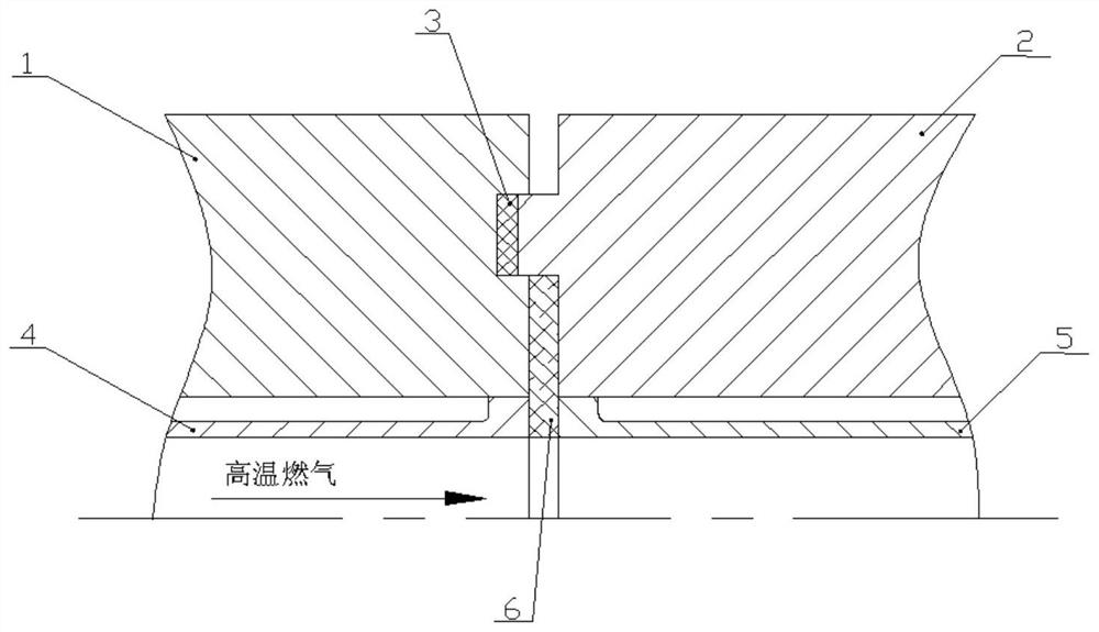
[0051] Such as figure 1 As shown, a flange sealing structure suitable for high temperature and large heat flow environment includes a first inner cylinder 4, a second inner cylinder 5, and matching groove flange 1 and tenon flange 2;

[0052] The groove of the groove flange 1 and the tenon of the tenon flange 2 respectively separate the butt end faces of the groove flange 1 and the tenon flange 2 into an inner butt end face and an outer butt end face;

[0053] The first inner cylinder 4 and the second inner cylinder 5 are respectively welded on the inner sides of the groove flange 1 and the tenon flange 2, and there is a gap between the two inner cylinders and the two flanges for filling cooling water to form a sandwich structure ; The butt end surfaces of the two inner cylinders are respectively flush with the inner butt end surface...


PUM


Abstract

The invention provides a flange sealing structure suitable for a high temperature and large heat flow environment and an installation method thereof, which solves the problems of inconvenient maintenance, high production and maintenance costs, and difficult reuse after damage of the existing integrated high temperature and large heat flow equipment. The sealing structure includes two inner cylinders, and matching groove flanges and tenon flanges; the groove and the tenon respectively separate the butt end faces of the two flanges into an inner end face and an outer end face; the two inner cylinders are welded on the two flanges respectively. On the inner side of each flange, there is a gap between the two inner cylinders and the two flanges, the end faces of the two inner cylinders are flush with the inner end faces of the two flanges respectively, and the wall surfaces of the two inner cylinders are flush or formed Steps along the airflow direction; gaskets are arranged in the groove, inorganic high temperature glue is arranged between the inner end faces of the two flanges and between the butt end faces of the two inner cylinders; An anti-adhesive layer that is easy to vaporize at high temperature is provided, and the thickness is not more than 0.1mm; the outer sides of the two flanges are fastened by fasteners.

Description

technical field [0001] The invention belongs to the sealing technology of high-temperature and large-heat flow equipment in the field of aerospace and aviation, and in particular relates to a flange sealing structure suitable for high-temperature and large-heat-flow environments and an installation method thereof. Background technique [0002] In recent years, with the rapid development of aerospace technology, especially the development of near-space hypersonic vehicles and reentry vehicles, higher requirements have been placed on the ablation resistance and thermal protection performance of materials. For this reason, advanced high temperature and large heat flow ground test equipment is needed to carry out research on the high temperature resistance characteristics of new materials. [0003] Existing high temperature and large heat flow equipment, in order to make it stable and reliable in the case of long-term scouring of gas flow above 3600K, so most of them adopt integ...

Claims


Application Information

Patent Timeline
Patent Type & Authority Patents(China)
IPC IPC(8): F16L23/032F16L23/18F16L23/024
CPCF16L23/024F16L23/032F16L23/18
Inventor 肖虹李小平房喜荣熊剑张晓军贺武生唐敏
Owner XIAN AEROSPACE PROPULSION INST
Learn More