Cross-platform MCU debugging method
A debugging method and cross-platform technology, which is applied in software testing/debugging, data processing input/output process, software deployment, etc., can solve the problem of inability to obtain the interdependence of system operation process modules, insufficient memory area values, and inability to obtain system operating status etc.
- Summary
- Abstract
- Description
- Claims
- Application Information
AI Technical Summary
Problems solved by technology
Method used
Image
Examples
Embodiment 1
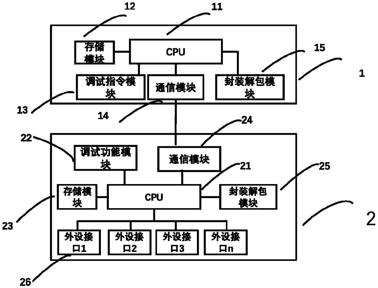
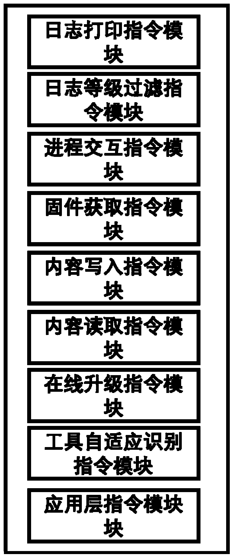
[0134] This embodiment provides a cross-platform MCU debugging device, see Figure 2 to Figure 4 , including host computer 1, MCU 2, host computer 1 includes CPU11, storage module 12, debugging instruction module 13, communication module 14, encapsulation and unpacking module 15, CPU11 respectively communicates with storage module 12, debugging module 13, communication module 14, encapsulation The unpacking module 15 is electrically connected, and the MCU 2 includes a CPU 21 , a debugging function module 22 , a communication module 24 , a storage module 23 , a packaging and unpacking module 25 , and at least one peripheral interface 26 .
[0135] The communication module 14 of host computer 1 is connected with the communication module 24 in the MCU, and wherein communication module 14 and communication module 24 all can adopt wireless communication or wired communication mode, if adopt wireless communication mode, wireless communication mode can WIFI, bluetooth, ultra-wide band...
Embodiment 2
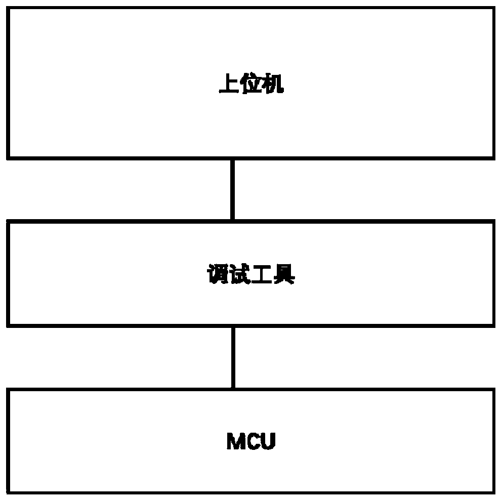
[0171] This implementation provides a cross-platform MCU debugging method, see Figure 5 and Figure 6 , which includes two stages. The first stage includes the host computer starting the debugging command and sending it to the MCU according to the debugging requirements. After receiving the debugging command, the MCU starts the corresponding debugging function module to debug the MCU;
[0172] The second stage includes sending the data generated by MCU debugging to the host computer for display. The data generated by MCU debugging includes at least logs, which are divided into multiple log levels according to the type. In the process of debugging the MCU, temporarily store the data that needs to be output in the memory, and wait for the external output when the system is idle. Or when it is found that the debugging function module in the MCU does not have a built-in preset function module or according to the debugging requirements, it is necessary to add a special function m...
Embodiment 3
[0201] This embodiment provides a data encapsulation and data unpacking method, which is completed by an encapsulation and unpacking module.
[0202] The data encapsulation method includes the following steps:
[0203] Step S701, obtaining the payload (payload) that needs to be packaged and obtaining the address, length, and data packet type of the payload therefrom;
[0204] Specifically, the payload that needs to be transmitted already exists, and it needs to be packaged when transmitting, and the payload can be transmitted according to the type of the data packet by adding a header;
[0205] Step S702, judging whether the address is valid, if the address is invalid, execute step S707, and end the packaging process; if the address is valid, execute step S703;
[0206]Specifically, since the load data is stored in segments, it is searched in the storage area according to the obtained address whether the address exists, and if the address exists, it means that the address is ...
PUM
 Abstract
Description
Claims
Application Information
 - R&D
- Intellectual Property
- Life Sciences
- Materials
- Tech Scout
- Unparalleled Data Quality
- Higher Quality Content
- 60% Fewer Hallucinations
Browse by: Latest US Patents, China's latest patents, Technical Efficacy Thesaurus, Application Domain, Technology Topic, Popular Technical Reports.
© 2025 PatSnap. All rights reserved.Legal|Privacy policy|Modern Slavery Act Transparency Statement|Sitemap|About US| Contact US: help@patsnap.com


