
Docking machinery of automatic crystal blank grinding and polishing system

A technology for docking machinery and blanks, which is applied in the direction of grinding/polishing equipment, grinding machines, spherical grinding machines, etc., and can solve problems such as increased assembly difficulty, high scrap rate, and crystal tilting

Pending Publication Date: 2019-11-15
曹建女
View PDF2 Cites 3 Cited by
  • Summary
  • Abstract
  • Description
  • Claims
  • Application Information

AI Technical Summary

Problems solved by technology

[0004] But the docking machine of this structure has the following defects at least during work: (1) due to the consistent action time of each station, when the first butt joint upper fixture seat is docked with the first butt joint lower fixture seat, the crystal is still If it is not glued firmly, it must be rotated vertically and exchanged with the second butt joint upper fixture seat and the second butt joint lower fixture, the crystal is prone to tilt, and the scrap rate is high; On the front side of the vertical turret, the second butt joint upper fixture seat and the second butt joint lower fixture seat are installed on the rear side of the vertical turret. During installation, it is necessary to adjust the corresponding positions of the two sets of butt joint fixture seats , its adjustment accuracy is high, which increases the difficulty of assembly; (3) Since the vertical turret needs to rotate vertically, the weight of the docking fixture seat installed on it should not be too heavy, but this will cause the two opposite docking fixture seats to be docked The effect is poor; (4) It takes time to flip, which affects the efficiency of the switchboard

Method used


Image

  • Docking machinery of automatic crystal blank grinding and polishing system
  • Docking machinery of automatic crystal blank grinding and polishing system
  • Docking machinery of automatic crystal blank grinding and polishing system

Examples


Embodiment Construction

[0029] In specific embodiments of the present invention, the orientations or positional relationships indicated by "up", "down", "left", "right", "front", "back" etc. are based on the orientations or positional relationships shown in the accompanying drawings, only It is for the convenience of describing the present invention and simplifying the description, but does not indicate or imply that the referred device or element must have a specific orientation, be constructed and operated in a specific orientation, and thus should not be construed as limiting the present invention.

[0030] like figure 1 As shown, the direction of arrow A is down, the direction of arrow B is up, the direction of arrow C is right, and the direction of arrow D is left; figure 2 As shown, the direction of the arrow E is the front, and the direction of the arrow F is the rear. This is for the convenience of description, and corresponding adjustments can be made in practice without affecting the connec...


PUM


Abstract

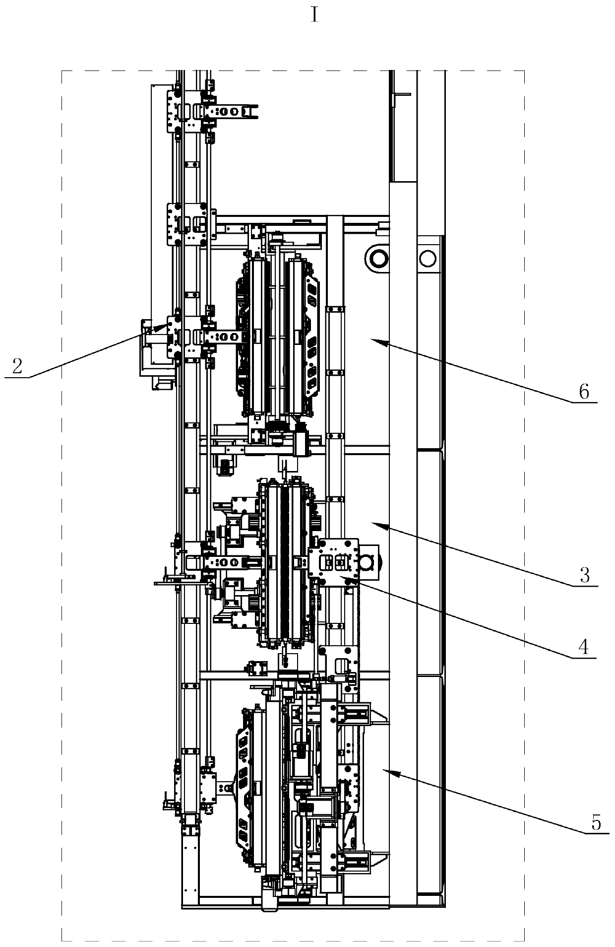
The invention relates to a docking machinery of an automatic crystal blank grinding and polishing system. The docking machinery comprises a rack, wherein a first left-right transferring mechanism, a docking upper fixture seat and a docking lower fixture seat are arranged on the front side of the rack; an up-down conversion station comprises a first upper fixture seat and a first lower fixture seatarranged on the left side of the docking upper fixture seat; a front-back conversion station comprises a second upper fixture seat and a second lower fixture seat arranged on the right side of the docking upper fixture seat; the docking machinery further comprises a first rotating rack and a second rotating rack; the first upper fixture seat and the first lower fixture seat realize up-down position exchange via rotation of the first rotating rack; and the second lower fixture seat is adjusted to the position, corresponding to the position of the second upper fixture seat, of the rear side ofthe rack via rotation of the second rotating rack. The docking machinery can rotate to the rear side of the rack to grind and polish a lower hemisphere after crystal is docked and glued firmly, and issimple in integrated structure, improved in rigidity, convenient to assemble, time-saving, improved in efficiency and excellent in docking effect.

Description

technical field [0001] The invention relates to the field of automatic grinding and polishing of crystal blanks, in particular to a docking machine for an automatic grinding and polishing system of crystal blanks. Background technique [0002] Chinese invention patent ZL201510094226.7 discloses an automatic grinding and polishing system for crystal blanks and its docking machine, which includes a first left-right transfer mechanism and a second left-right transfer mechanism arranged in parallel, along the first left-right transfer mechanism from right to left There are loading and unloading stations, a plurality of upper hemisphere grinding and polishing stations and docking stations arranged in a row, and a docking station, multiple lower hemisphere grinding and polishing stations and loading and unloading stations are arranged in sequence from left to right along the second left and right transfer mechanisms. station; wherein, the loading and unloading station is provided ...

Claims


Application Information

Patent Timeline
IPC IPC(8): B24B11/02B24B27/00B24B41/00B24B41/06
CPCB24B11/02B24B27/0023B24B41/005B24B41/06
Inventor 曹建女
Owner 曹建女
Learn More