A cross-cut sawing machine
What is Al technical title?
Al technical title is built by PatSnap Al team. It summarizes the technical point description of the patent document.
A technology of horizontal cutting and sawing machine, applied in sawing machine device, metal sawing equipment, metal processing equipment and other directions, can solve the problems of difficult forging and processing, reduce production efficiency, waste raw materials, etc., to avoid bending, prolong service life, improve The effect of cutting precision
Active Publication Date: 2020-09-22
星泓智造装备有限公司
View PDF7 Cites 0 Cited by
Summary
Abstract
Description
Claims
Application Information
AI Technical Summary
This helps you quickly interpret patents by identifying the three key elements:
Problems solved by technology
Method used
Benefits of technology
Problems solved by technology
However, some flanges and bearings have high requirements for product height and performance. However, due to their weight and the ability of ring rolling equipment, forging and processing are relatively difficult. Therefore, rings with very small heights are currently The parts are all heightened (sometimes doubled), and finally all the margins are processed by processing methods to meet the height of the final product, which will waste raw materials and increase costs and reduce production efficiency.
[0003] In the early stage of development, the blanking sawing machine was modified. The size of the cutting ring has size requirements. The rotation of the chuck is driven by the motor. The clamping method is clamped by mechanical claws. The operating position of the saw blade is to cut from top to bottom. In the process of cutting the product, the rotation speed needs to be manually adjusted. The product is relatively stable at the beginning of the rotation, but it slides down as time goes by. The saw blade has a reverse force during the cutting process, and its verticality difference is relatively large. , and when the product is about to be cut, there is a sawing phenomenon due to the internal stress of the product. When this phenomenon occurs, a saw blade will be scrapped or the cutting will be re-entered, which will increase the cost and reduce the production efficiency. After working for a long time, there is a place at the back that is worn out. For this reason, we propose a cross-cut sawing machine
Method used
Image
Click on the blue label to locate the original text in one second.
Reading with bidirectional positioning of images and text.
Examples
Embodiment Construction
[0017] The following will clearly and completely describe the technical solutions in the embodiments of the present invention with reference to the accompanying drawings in the embodiments of the present invention. Obviously, the described embodiments are only some, not all, embodiments of the present invention. Based on the embodiments of the present invention, all other embodiments obtained by persons of ordinary skill in the art without making creative efforts belong to the protection scope of the present invention.
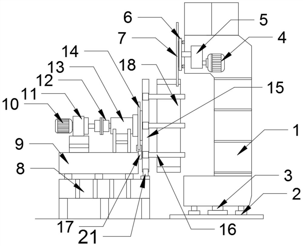
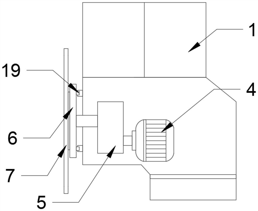
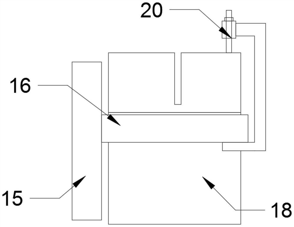
[0018] see Figure 1-4 , the present invention provides a technical solution: a cross-cut sawing machine, including a frame 1, a needle guide rail 2, an anti-skid mechanism 3, a motor 4, a driven gear 6, a saw blade 7, a frame 8, a seat 9, a motor 10, Reducer 11, coupling 12, oiling device 13, brake disc 14, chuck turntable 15, vise claw 16, clamp brake 17, ring 18, clamp 20 and supporting wheel 21, the bottom of frame 1 passes through The needle guide rail 2...
PUM
Abstract
The invention discloses a transverse cutting sawing machine. The transverse cutting sawing machine comprises a frame, a rolling needle guide rail, an anti-skid mechanism, a motor, a driven gear, a sawblade, a frame table, a seat stand, a motor, a speed reducer, a coupling, an oil injecting device, a brake disc, a chuck rotary table, a vice clamping jaw, a clamping type brake, a ring part, a clampand a riding wheel, wherein the bottom of the frame is in sliding connection with a bottom plate through the rolling needle guide rail. The clamping type brake and the brake disc are adjusted by thedevice to enable the ring part to be clamped stably, so that the saw blade reactive force is reduced stably, the installation of a guiding block is matched, so that the cutting of the saw blade is stable, the saw blade is prevented from shaking, the cutting precision is improved, the service life of the saw blade is prolonged, the clamping of the clamp facilitates the stable position limitation ofthe ring part, and the phenomenon that the clamping force is caused to the cutting part when penetrative cutting is conducted on the ring part by the saw blade is avoided; and the supporting on the chuck rotary table is increased through the clamping type brake, the chuck rotary table is prevented from being bent by the pressure of the ring part, and the machining precision is improved.
Description
technical field [0001] The invention relates to a cross-cut sawing machine for segmenting rings, which belongs to the field of engineering equipment, in particular to a cross-cut sawing machine. Background technique [0002] Large-scale ring forgings are one of the important links in the development and production of wind power and large-scale equipment in my country. As manufacturers of wind power supporting facilities such as flanges, bearings, brake discs and yaw rings, they have good market prospects and development space. However, some flanges and bearings have high requirements for product height and performance. However, due to their weight and the ability of ring rolling equipment, forging and processing are relatively difficult. Therefore, rings with very small heights are currently The parts are all heightened (sometimes doubled), and finally all the margins are processed by processing methods to meet the height of the final product, which will waste raw materials ...
Claims
Application Information
Patent Timeline
Application Date:The date an application was filed.
Publication Date:The date a patent or application was officially published.
First Publication Date:The earliest publication date of a patent with the same application number.
Issue Date:Publication date of the patent grant document.
PCT Entry Date:The Entry date of PCT National Phase.
Estimated Expiry Date:The statutory expiry date of a patent right according to the Patent Law, and it is the longest term of protection that the patent right can achieve without the termination of the patent right due to other reasons(Term extension factor has been taken into account ).
Invalid Date:Actual expiry date is based on effective date or publication date of legal transaction data of invalid patent.
