
Thermal shrinkage fusion welding splicing sleeve and splicing structure thereof

A heat-shrinkable sleeve and connecting structure technology, applied in the direction of connection, connection insulation, conductive connection, etc., to achieve good operability and reliability, avoid welding virtual welding and external insulation protection, good immersion effect

Inactive Publication Date: 2019-11-12
BEIJING HANGKE ENGINE CONTROL SYST SCI & TECH
View PDF2 Cites 0 Cited by
  • Summary
  • Abstract
  • Description
  • Claims
  • Application Information

AI Technical Summary

Problems solved by technology

[0004] The invention designs a wire connection structure using prefabricated solder heat shrinkage welding, which solves the reliability and stability problems of wire connection during the repair process of the electronic control parts of the aircraft engine fuel system

Method used


Image

  • Thermal shrinkage fusion welding splicing sleeve and splicing structure thereof
  • Thermal shrinkage fusion welding splicing sleeve and splicing structure thereof
  • Thermal shrinkage fusion welding splicing sleeve and splicing structure thereof

Examples


Embodiment Construction

[0032] The present invention is described in further detail below by specific embodiment:

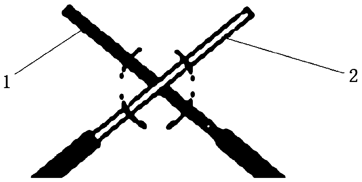
[0033] Such as figure 1 As shown, there is provided a heat shrinkable welding connection structure, including a first connection end, a second connection end and a heat shrinkable sleeve; the first connection end and the second connection end are cross-overlapped, and the first connection end Wrap the same number of turns with the second connecting end from the overlapping point to each other to form a winding overlapping structure; the heat shrinkable sleeve is fixed with solder, and a through hole is opened in the middle of the solder; the winding overlapping structure is located at the In the through hole of the solder; and by being heated, the solder is melted and integrated with the winding lap structure, so that the heat-shrinkable sleeve heat-shrinks and hugs the solder. The heat-shrinkable sleeve is filled with waterproof hot-melt adhesive, and the waterproof hot-melt adhesive ...


PUM

PropertyMeasurementUnit
Apertureaaaaaaaaaa
Outer diameteraaaaaaaaaa

Abstract

The invention relates to a thermal shrinkage fusion welding splicing sleeve and a splicing structure thereof. The thermal shrinkage fusion welding splicing sleeve comprises a first splicing end, a second splicing end and a thermal shrinkage sleeve, the first splicing end and the second splicing end are in cross lap joint with each other, and the first splicing end and the second splicing end are wound by the same number of turns towards each other from the lap joint point to form a winding lap joint structure. Solder is fixed in the thermal shrinkage sleeve, and a through hole is formed in themiddle of the solder. The winding lap joint structure is located in the through hole of the solder. Through heating, the solder is subjected to hot melting to be integrated with the winding lap jointstructure, so that the thermal shrinkage sleeve is subjected to heat shrinkage to enclasp the solder. The integrated thermal shrinkage fusion welding splicing structure is designed, so welding, insulation and thermal shrinkage protection operations are integrated through hot air, the immersion of a soldering tin material is good, the conditions of traditional welding pseudo soldering, no insulation protection outside and the like are avoided, and the structure has good operability and reliability.

Description

technical field [0001] The invention relates to the technical field of small-section electric equipment wiring for aero-engines, and relates to the small-section direct connection (wire diameter and cross-section diameter less than 0.38mm) 2 ) wire connection design, specifically relates to a thermal shrinkage welding connection sleeve and its connection structure. Background technique [0002] Functional components such as electro-hydraulic servo valves, solenoid valves, displacement sensors, and temperature sensors are widely used in the engine fuel control system. Due to the overall layout and wire integration requirements, the lead wires of general electrical functional components need to be aggregated to the electrical socket for clustering. Frequent disassembly and assembly are prone to insufficient wire length or partial damage. Electrical functional components are high-value products, and wire extension operations are unavoidable during repairs. The traditional wire...

Claims


Application Information

Patent Timeline
IPC IPC(8): H01R4/72H01R4/14
CPCH01R4/14H01R4/723
Inventor 李学明李崇喻阳袁树峥
Owner BEIJING HANGKE ENGINE CONTROL SYST SCI & TECH
Learn More