Propeller shaft remote sensing type strain measuring system used for ship, measuring device, and measuring method
A technology of strain measurement and propulsion shaft, applied in measurement devices, testing of mechanical parts, testing of machine/structural parts, etc., can solve the problems of no landing products, shaft power monitoring equipment staying in the theoretical stage, etc., to avoid the measurement value The effect of small size and easy installation
- Summary
- Abstract
- Description
- Claims
- Application Information
AI Technical Summary
Problems solved by technology
Method used
Image
Examples
Embodiment 1
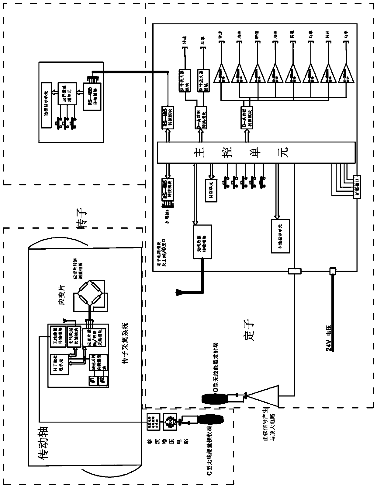
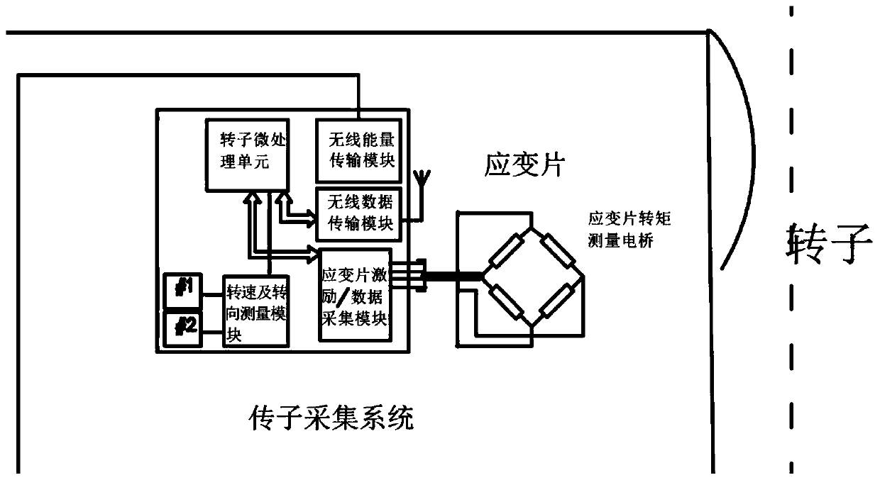
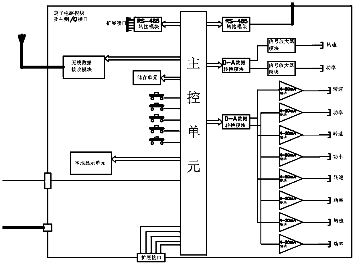
[0065] refer to figure 1 As shown, a marine propulsion shaft remote-sensing strain measurement system is provided, which is used for the measurement of metal and / or non-metallic transmission shafts, including: a rotor acquisition system, which includes a stress gauge torque measurement electronic set on the transmission shaft under test Bridge and speed / steering sensor, 24-Bit ultra-high-precision AD data converter ADS1255, high-precision voltage reference chip and instrument signal amplifier module INA128, used to detect the micro-strain signal and speed / steering signal of the transmission shaft, and The detected micro-strain signal and rotational speed / turn signal are sent to the stator analysis system through a wireless data transmission module (Zigbee wireless module); a stator analysis system is used to receive the micro-strain signal and rotational speed transmitted by the rotor module / steering signal, and utilize the main control unit to analyze and process it, store a...
Embodiment 2
[0074] refer to Figure 5-7 As shown, this embodiment provides a marine propulsion shaft remote sensing strain measurement device based on the system, which includes a rotor acquisition device 100 and a stator device composed of a wireless induction power supply device 200 and a stator analysis device 300. The wireless induction The power supply device 200 and the stator analysis device 300 are located on the top of the support frame 400, wherein: the wireless induction power supply device 200 uses OC-type coil winding wireless power supply and power supply excitation to provide the torque measurement strain gauge 120, rotor circuit board 130 and The speed / steering sensor 140 provides power; the micro-strain signal and the speed / steering signal of the transmission shaft 500 are collected and detected in real time by the rotor acquisition device 100, and the detected micro-strain signal and the speed / steering signal are wirelessly sent to the stator for analysis device 300; and...
Embodiment 3
[0084] see Figure 9 As shown, a kind of marine propulsion shaft remote sensing type strain measurement method based on the measuring device is provided, comprising the steps:
[0085] S1, pasting and installing the torque measuring strain gauge 120 on the transmission shaft 500;
[0086] S2, connecting the torque measuring strain gauge 120 to the rotor circuit board 130 of the rotor acquisition device 100 through a cable;
[0087] S3, sleeve the rotor collection device 100 on the transmission shaft 500 through the rotor collar 110;
[0088] S4, installing the rotor excitation C-shaped coil 230 of the wireless induction power supply device 200 on the surface of the rotor collar 110;
[0089] S5, align the stator excitation O-shaped coil 220 of the wireless induction power supply device 200 with the surface of the rotor collar 110 to ensure that the wireless power supply signal is normal;
[0090] S6, turning on the power supply, so that the rotor collecting device 100 and t...
PUM
 Abstract
Description
Claims
Application Information
 - R&D
- Intellectual Property
- Life Sciences
- Materials
- Tech Scout
- Unparalleled Data Quality
- Higher Quality Content
- 60% Fewer Hallucinations
Browse by: Latest US Patents, China's latest patents, Technical Efficacy Thesaurus, Application Domain, Technology Topic, Popular Technical Reports.
© 2025 PatSnap. All rights reserved.Legal|Privacy policy|Modern Slavery Act Transparency Statement|Sitemap|About US| Contact US: help@patsnap.com


