
Cleaning equipment for kitchen range hood

A technology for cleaning equipment and range hoods, which is applied to the removal of lampblack, lighting and heating equipment, cleaning methods and utensils, etc., which can solve the problems of heavy use burden, increased cleaning difficulty, and difficult cleaning, so as to achieve improved cleaning effect and good working functions , The effect of simple equipment structure

Active Publication Date: 2019-11-12
刘彬
View PDF4 Cites 0 Cited by
  • Summary
  • Abstract
  • Description
  • Claims
  • Application Information

AI Technical Summary

Problems solved by technology

[0002] The range hood equipment will produce a lot of oil pollution when it is working. Since the range hood is set at a high position, when cleaning, personnel have to raise their hands or disassemble the range hood, and then clean the oil-contaminated part of the range hood Efficient cleaning increases the difficulty of cleaning equipment to a large extent. At the same time, when personnel clean equipment at a higher position, they will also waste energy due to the long-term high-position work, and continue to work. It is easy to cause overwork, and the existing range hood cleaning equipment has many disadvantages, such as: it is impossible to form a bracket to support the cleaning equipment, so that the practicability of the equipment is low when it is working, and the burden on personnel is heavy. The existing equipment cannot be unfolded to form a stable support. It is difficult to clean the range hood on some kitchen countertops, and the solvent after cleaning cannot be recovered conveniently.

Method used


Image

  • Cleaning equipment for kitchen range hood
  • Cleaning equipment for kitchen range hood
  • Cleaning equipment for kitchen range hood

Examples


Embodiment Construction

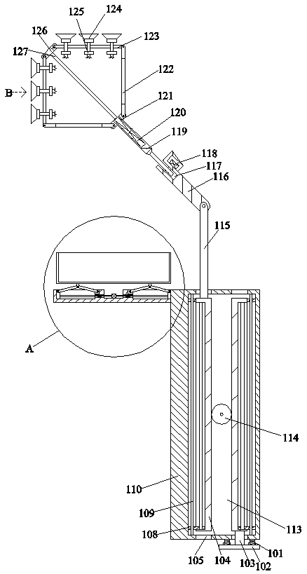
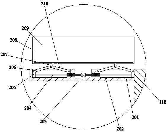
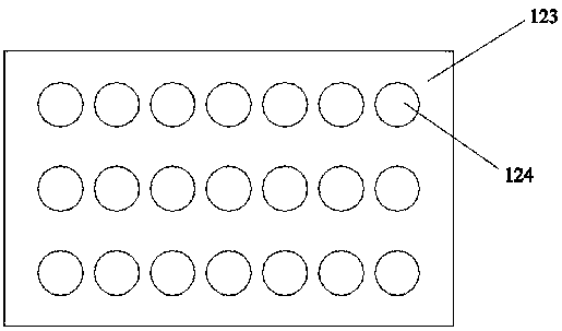
[0020] Such as Figure 1-Figure 3 As shown, the present invention is described in detail. For the convenience of description, the orientations mentioned below are now stipulated as follows: figure 1 The up, down, left, right, front and back directions of the projection relationship are the same. A kitchen range hood cleaning device of the present invention includes a box body 110, and the left end of the box body 110 is provided with a holding device for holding the cleaned solvent. The box body 110 is provided with a cavity 113, and the upper and lower end walls of the cavity 113 are connected with a symmetrical inner cavity 105, and the inner cavity 105 is connected with the external space. The expansion device supported by the equipment, the upper side of the expansion device is provided with a liquid spraying device for spraying liquid from multiple angles.

[0021] Beneficially, the storage device includes a side installation box 201 fixed to the box body 110, a symmetri...


PUM


Abstract

The invention discloses cleaning equipment for a kitchen range hood. The cleaning equipment comprises a box body; a containing device for containing a cleaned solvent is arranged at the left end surface of the box body; a containing cavity is formed in the box body; symmetrical inner cavities are formed in the upper end wall and the lower end wall of the containing cavity in a communicating manner; the inner cavities communicate with an external space; an expanding device capable of expanding to support the equipment is arranged in the containing cavity; and a liquid spraying device for spraying liquid at multiple angles is arranged on the upper side of the expanding device. The cleaning equipment is simple in structure; a mode of supporting the cleaning equipment on a kitchen worktable and the ground is adopted, so that personnel are able to conveniently use the cleaning equipment without lifting the cleaning equipment, waste liquid after cleaning is capable of being efficiently recycled; and meanwhile, the angle and the orientation of the sprayed liquid can be adjusted, so that the cleaning equipment has a good working function, and the cleaning effect of the personnel on the range hood is improved.

Description

technical field [0001] The invention relates to the technical field of range hood cleaning equipment, in particular to kitchen range hood cleaning equipment. Background technique [0002] The range hood equipment will produce a lot of oil pollution when it is working. Since the range hood is set at a high position, when cleaning, personnel have to raise their hands or disassemble the range hood, and then clean the oil-contaminated part of the range hood Efficient cleaning increases the difficulty of cleaning equipment to a large extent. At the same time, when personnel clean equipment at a higher position, they will also waste energy due to the long-term high-position work, and continue to work. It is easy to cause overwork, and the existing range hood cleaning equipment has many disadvantages, such as: it is impossible to form a bracket to support the cleaning equipment, so that the practicability of the equipment is low when it is working, and the burden on personnel is he...

Claims


Application Information

Patent Timeline
IPC IPC(8): F24C15/20B08B3/02B08B13/00
CPCB08B3/02B08B13/00F24C15/2057
Inventor 王芳
Owner 刘彬
Learn More