
Swing suppression energy dissipation device

An energy-consuming device and energy-consuming technology, applied in the field of new anti-galloping devices, can solve the problems of lack of self-adjustment function and limited amplitude of vibration suppression, achieve good anti-galloping control effect, change singleness and limitations, and have obvious effects. Effect

Active Publication Date: 2019-11-12
SHANDONG UNIV
View PDF8 Cites 6 Cited by
  • Summary
  • Abstract
  • Description
  • Claims
  • Application Information

AI Technical Summary

Problems solved by technology

However, the inventor found that the anti-galling and vibration reduction control used on transmission lines in actual engineering is mostly passive control. Considering the influence of various factors, passive control has certain limitations, lacks self-regulation function, and suppresses the amplitude of vibration. Limited, unable to meet the requirements of UHV, long-distance and long-span power transmission in the current power industry

Method used


Image

  • Swing suppression energy dissipation device
  • Swing suppression energy dissipation device
  • Swing suppression energy dissipation device

Examples


Embodiment Construction

[0038] It should be pointed out that the following detailed description is exemplary and intended to provide further explanation to the present application. Unless defined otherwise, all technical and scientific terms used herein have the same meaning as commonly understood by one of ordinary skill in the art to which this application belongs.

[0039] It should be noted that the terminology used here is only for describing specific implementations, and is not intended to limit the exemplary implementations according to the present application. As used herein, unless the context clearly dictates otherwise, the singular is intended to include the plural, and it should also be understood that when the terms "comprising" and / or "comprising" are used in this specification, they mean There are features, steps, operations, means, groups and / or combinations thereof;

[0040] For the convenience of description, if the words "up", "down", "left" and "right" appear in the present inven...


PUM


Abstract

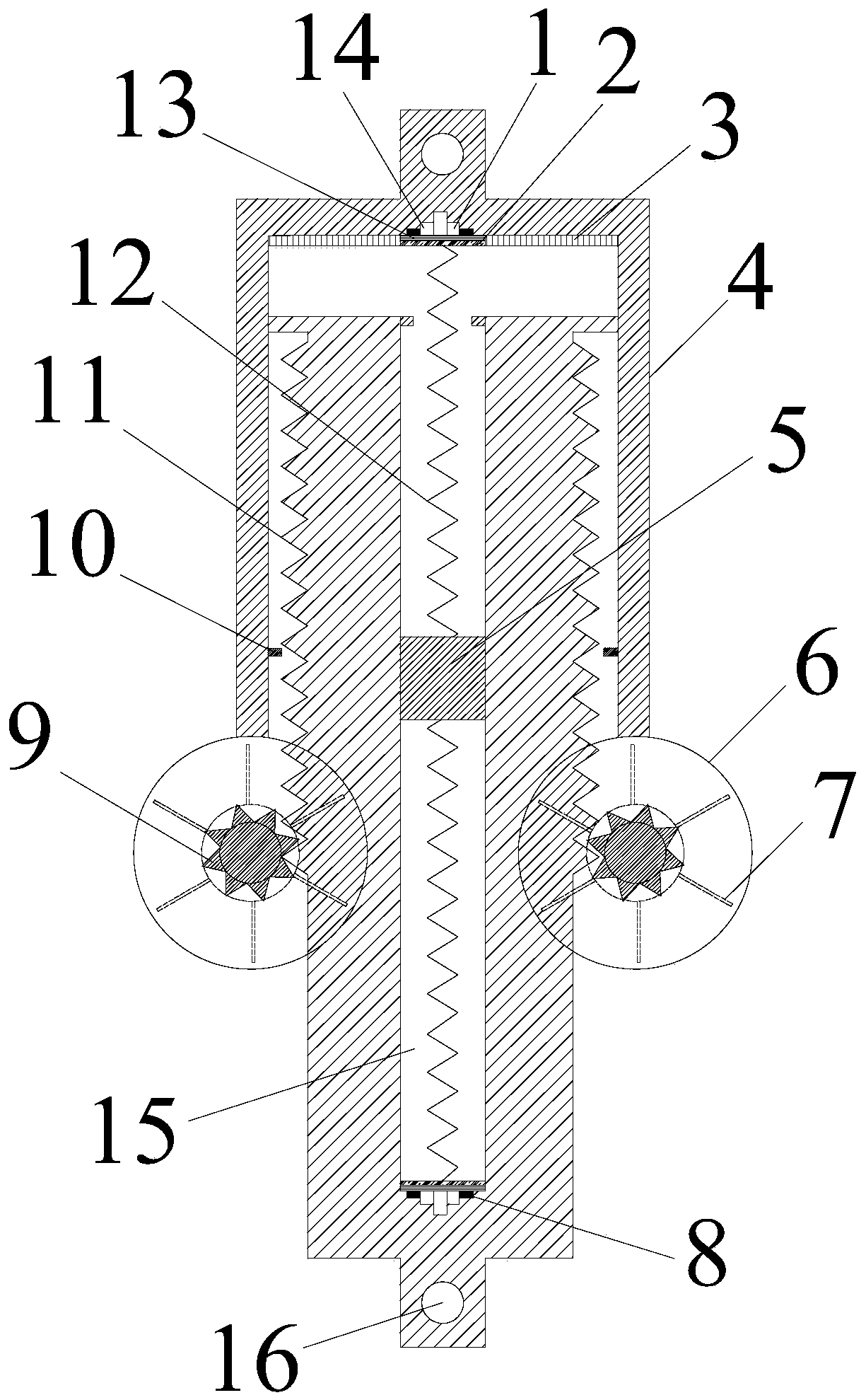
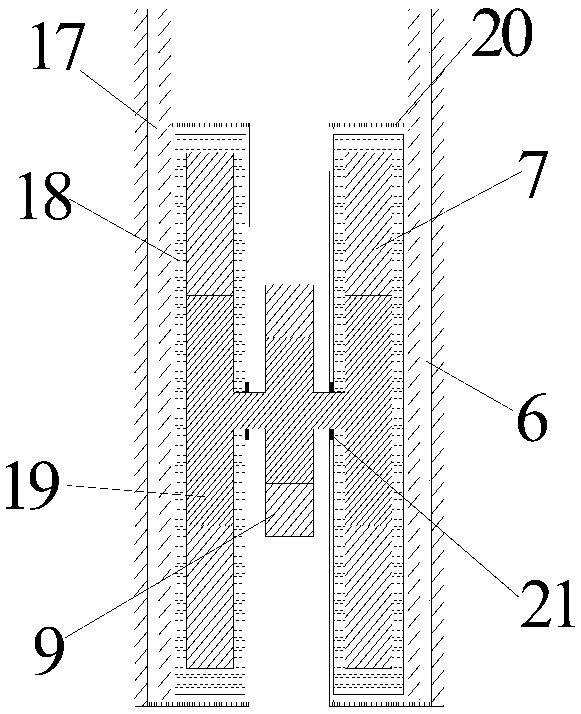
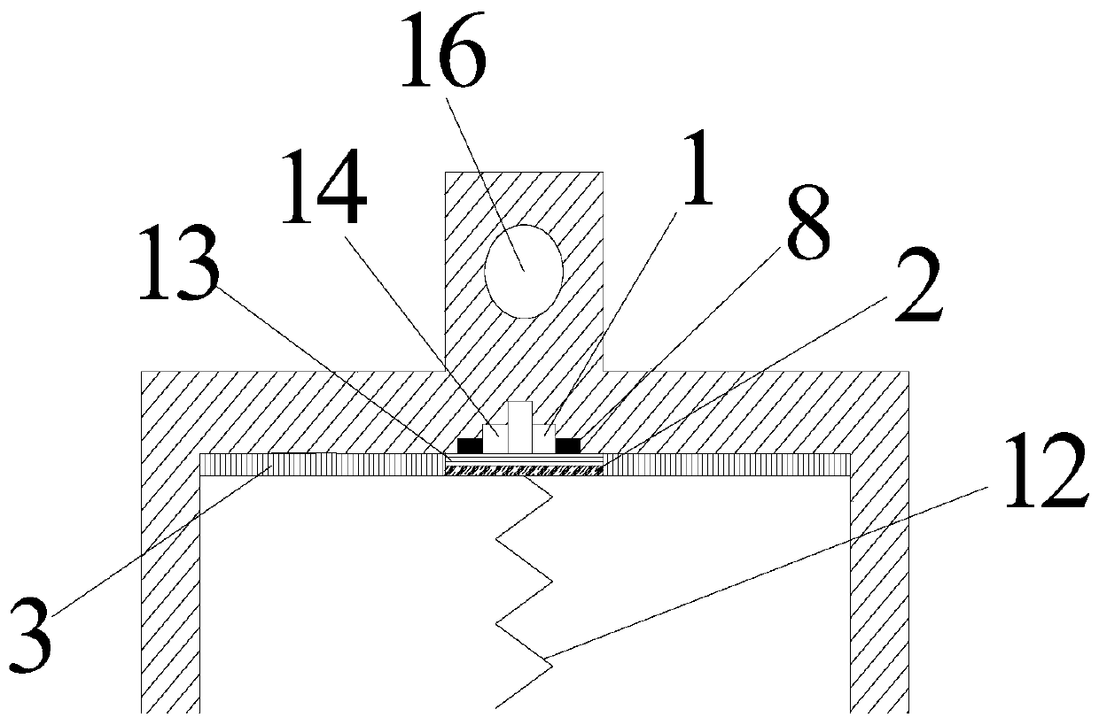
The invention discloses a swing suppression energy dissipation device. The swing suppression energy dissipation device comprises a connection part and an energy dissipation part. The left and right sides of the energy dissipation part are each provided with an energy dissipation cylinder. The left and right energy dissipation cylinders belong to airtight cylindrical tubes. The energy dissipation cylinders contain magneto-rheological fluid. A magnet exciting coil is coiled on the periphery of each cylindrical tube and connected with a piezoelectric unit. The cylindrical tubes on the two sides are each internally provided with a rolling wheel. A gear is arranged between the two cylindrical tubes. The rolling wheels and the gear are fixed through a connecting shaft and can rotate coaxially. The connection part is composed of a hollow box-type tube in the middle and toothed plates on the left and right sides. Piezoelectric power generation units are arranged at the bottom end of the hollowbox-type tube and in the middle position of the interior of a main body of the energy dissipation part correspondingly. The two ends of each piezoelectric power generation unit are provided with pressure sensors. The box-type tube is internally provided with a mass body. The mass body is connected with the two ends of the box-type tube through springs. The toothed plates of the connection part are engaged with the gear of the energy dissipation part. The periphery of the whole energy dissipation part is totally enclosed.

Description

technical field [0001] The invention relates to a novel anti-galling device, in particular to the technology of suppressing galloping and energy consumption of a power transmission line, which mainly controls the galloping phenomenon of the power transmission line under the action of wind load. Background technique [0002] Galloping of transmission lines will occur when the surrounding ice is covered and side wind acts. The galloping of transmission lines is a problem that must be paid attention to in the process of power transmission and needs to be solved seriously, because galloping of transmission lines will cause various hazards. For example, it will cause the breakage of the wire, damage the restraint device at the connection part of the wire, make the connecting bolt fall off, even cause the toppling of the transmission tower, and cause a serious electric safety accident. [0003] Aiming at the problem of galloping of transmission lines, various technical measures ha...

Claims


Application Information

Patent Timeline
Patent Type & Authority Applications(China)
IPC IPC(8): F16F13/06F16F13/30H02G7/14
CPCF16F13/06F16F13/305H02G7/14
Inventor 田利刘文棚周梦瑶毕文哲
Owner SHANDONG UNIV
Learn More