
Cutting depth self-adjusting mechanism and drill bit

A cutting depth, self-adjusting technology, used in drill bits, earthwork drilling, drilling equipment, etc., can solve problems such as low drilling efficiency, stick-slip vibration, etc., to overcome the fixed cutting depth, prevent damage and twist break, The effect of expanding the stable operating area

Pending Publication Date: 2019-11-12
KINGDREAM PLC CO +1
View PDF0 Cites 2 Cited by
  • Summary
  • Abstract
  • Description
  • Claims
  • Application Information

AI Technical Summary

Problems solved by technology

[0004] One of the purposes of this application is to provide a cutting depth self-adjusting mechanism and a drill bit, aiming to improve the problem that the drill bit in the prior art is prone to stick-slip vibration when drilling through different formations, resulting in low drilling efficiency

Method used


Image

  • Cutting depth self-adjusting mechanism and drill bit
  • Cutting depth self-adjusting mechanism and drill bit
  • Cutting depth self-adjusting mechanism and drill bit

Examples


no. 1 example

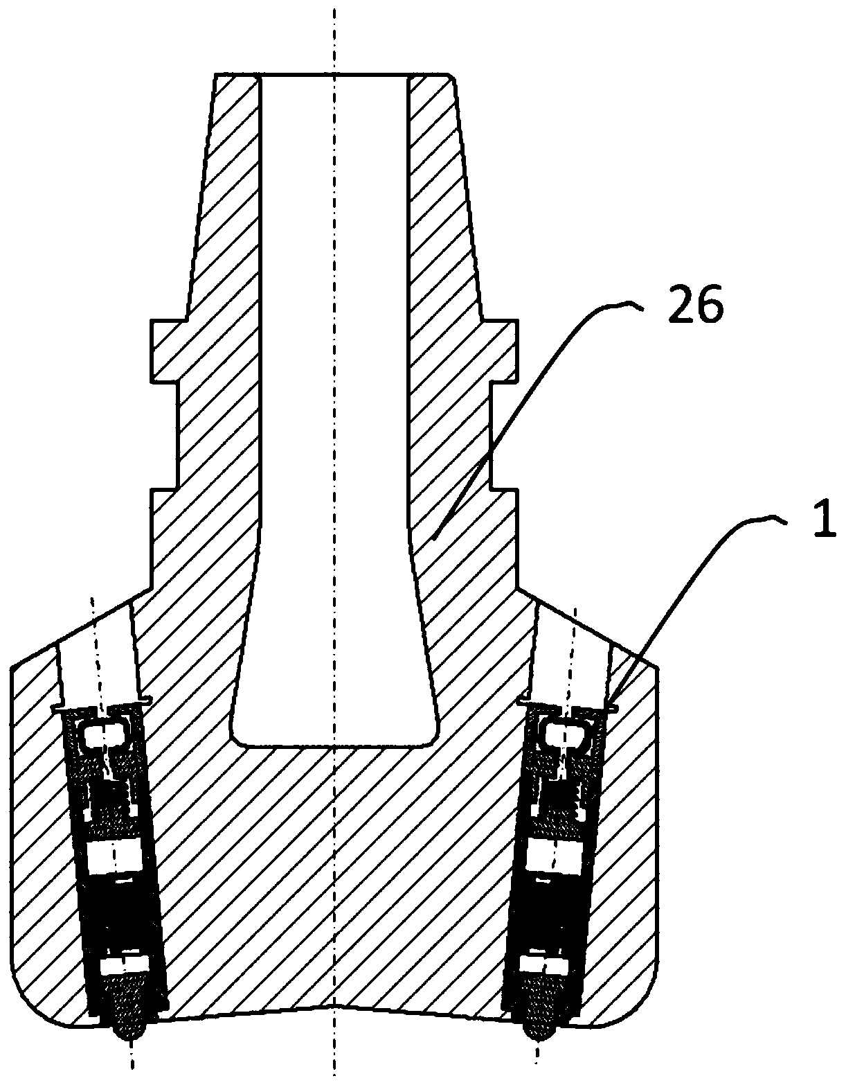
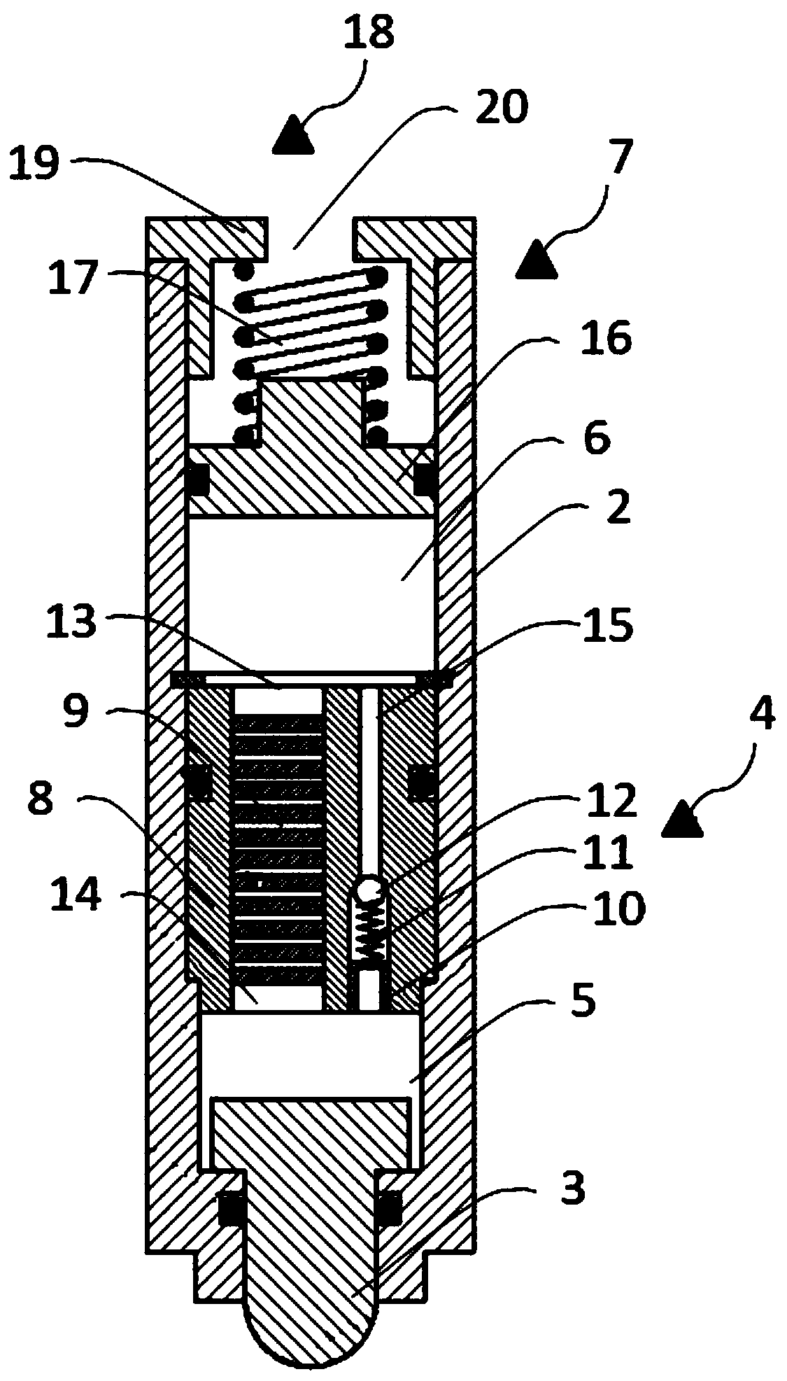
[0035] Please refer to figure 1 , with reference to figure 2 , the embodiment of the present application provides a drill bit 26, the blades on both sides of the drill bit 26 are respectively symmetrically installed with a cutting depth self-adjusting mechanism 1, which is mainly used for adjusting the cutting depth of the drill bit 26, and can effectively prevent the drill bit 26 from stick-slip In the case of vibration, the combination between the cutting teeth of the drill bit 26 and the bottom hole can be protected, the footage of the drill bit 26 can be extended, and the safety of drilling construction can be improved, thereby effectively improving the efficiency and benefit of drilling construction.

[0036] It should be noted that, in this embodiment, the drill bit 26 may be a PDC drill bit.

[0037] Please refer to figure 2The cutting depth self-adjusting mechanism 1 mainly includes an outer cylinder 2, a ball tooth 3, a throttling damping valve 4 and a hydraulic r...

no. 2 example

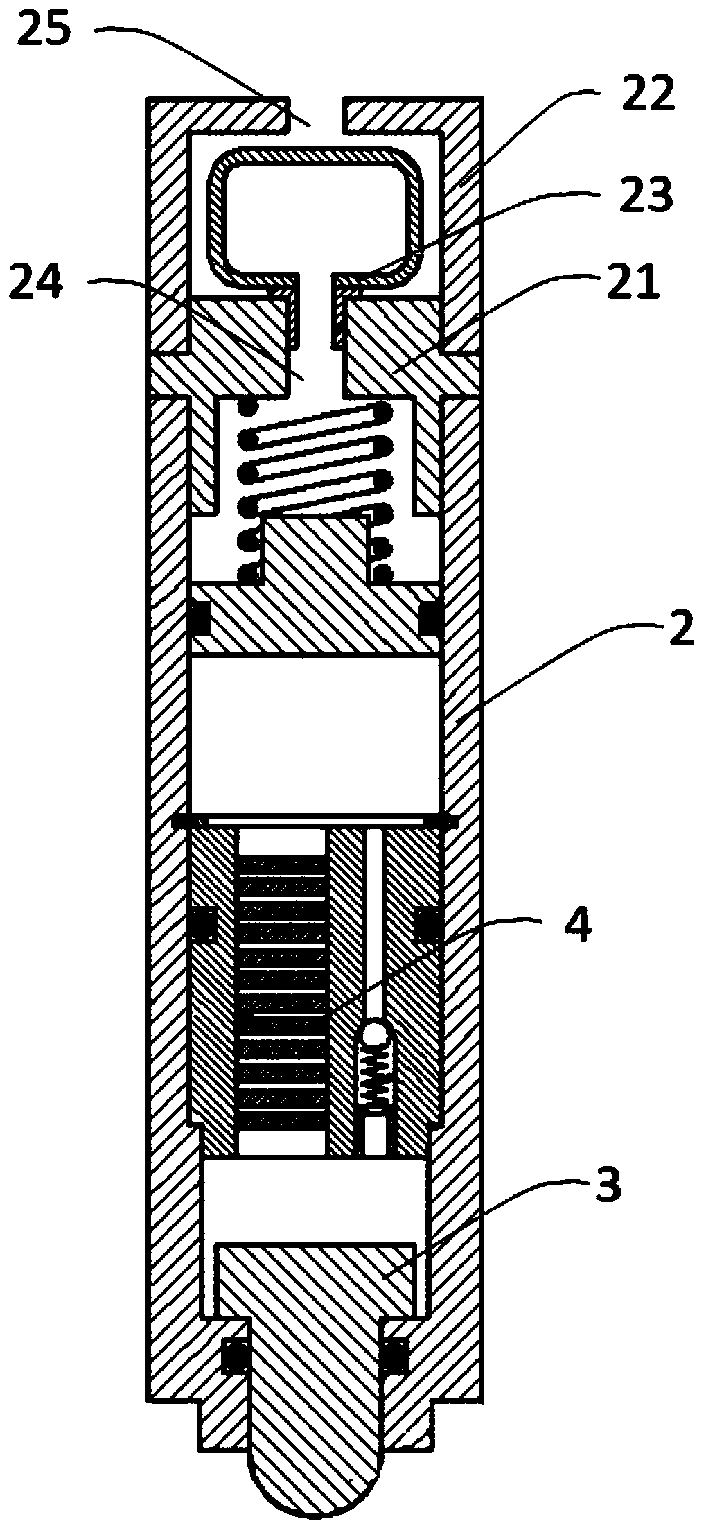
[0056] Please refer to image 3 , the embodiment of the present application provides another structure of the cutting depth self-adjusting mechanism 1 and the drill bit 26, most of its structure is the same as that of the first embodiment, the difference is that the protection structure 18 in the present application is different from that in the first embodiment is different.

[0057] It should be noted that, in this embodiment, the protective structure 18 includes a mounting cover 21, a protective cover 22 and a rubber bladder 23; the mounting cover 21 is mounted on the other end of the outer cylinder 2, and the mounting cover 21 is provided with a second opening 24 , the other end of the return spring 17 is crimped on the mounting cover 21; the protective cover 22 is set on the mounting cover 21 through a threaded connection cover, and the protective cover 22 is provided with a third opening 25; the rubber bladder 23 is arranged in the protective cover 22 , and connected to...


PUM


Abstract

The invention provides a cutting depth self-adjusting mechanism and a drill bit, and belongs to the field of oil exploitation. The cutting depth self-adjusting mechanism comprises an outer cylinder, aball head tooth, a throttle damping valve and a hydraulic reset assembly, wherein the ball head tooth is movably installed at one end of the outer cylinder and can retract in or extend out of the outer cylinder; the throttle damping valve is installed in the outer cylinder, and divides an inner cavity of the outer cylinder into a first hydraulic cavity and a second hydraulic cavity, wherein the first hydraulic cavity and the second hydraulic cavity are filled with hydraulic fluid; and the hydraulic reset assembly is movably installed at the other end of the outer cylinder and can move under the driving of the hydraulic fluid in the second hydraulic cavity. Through the double damping function of the throttle damping valve and the hydraulic reset assembly, the impact on the bit by the rockis reduced, cutting teeth of the bit are further protected, the bit footage is increased, and the bit service time is prolonged.

Description

technical field [0001] The application relates to the field of oil exploitation, in particular to a cutting depth self-adjusting mechanism and a drill bit. Background technique [0002] During the drilling process, the drill bit needs to drill through different formations. When the formation lithology changes, the drilling speed will change accordingly, which will easily cause the stick-slip vibration of the drill bit, and even cause the failure of the drill bit and the downhole drilling tool assembly, resulting in increased drilling costs and reduced efficiency due to complex accidents at the bottom of the well. Usually, the drilling speed is mainly achieved by controlling the drilling pressure and rotation speed, that is, respectively through hook load, drill string rotation, or controlling the speed of the bottom hole motor, but these control methods have a certain hysteresis for the bottom hole drill bit . [0003] With the rapid development of PDC bit technology, in o...

Claims


Application Information

Patent Timeline
Patent Type & Authority Applications(China)
IPC IPC(8): E21B10/62E21B10/43E21B10/54
CPCE21B10/62E21B10/43E21B10/54
Inventor 吴文邵增元周悦辉
Owner KINGDREAM PLC CO
Learn More