
Ku waveband comprehensive radio frequency transceiving system

A radio frequency transceiver, ku-band technology, applied in the field of Ku-band integrated radio frequency transceiver system, can solve the problems of low radio frequency integration, single waveform, and reduced product reliability, and achieve high receiving sensitivity, high power output, and high dynamic range Effect

Pending Publication Date: 2019-11-08
GUANGDONG SHENGDA ELECTRONICS
View PDF0 Cites 12 Cited by
  • Summary
  • Abstract
  • Description
  • Claims
  • Application Information

AI Technical Summary

Problems solved by technology

[0009] In the early RF development, due to the single function of microwave devices, it was easy to implement a single-function RF hardware system. To realize a multi-functional integrated system, it is necessary to use multiple sets of subsystem stacking, which increases the complexity and cost of research and development, and reduces the reliability of the product.
However, once the design and production of a single-function RF hardware system is completed, the specific implementation functions and technical parameters are fixed, and it is difficult to achieve horizontal function expansion.
[0010] The comprehensive radio frequency system that has appeared so far is not high in radio frequency integration, and only slightly expands on the basis of the main functional modules to achieve some additional auxiliary functions. In fact, the degree of hardware reuse is still low
[0011] The traditional microwave frequency source is only designed for a single-function RF module, with low degree of flexible configuration, facing problems such as single waveform, no modulation function, and insufficient frequency hopping bandwidth.

Method used


Image

  • Ku waveband comprehensive radio frequency transceiving system
  • Ku waveband comprehensive radio frequency transceiving system
  • Ku waveband comprehensive radio frequency transceiving system

Examples


Embodiment 1

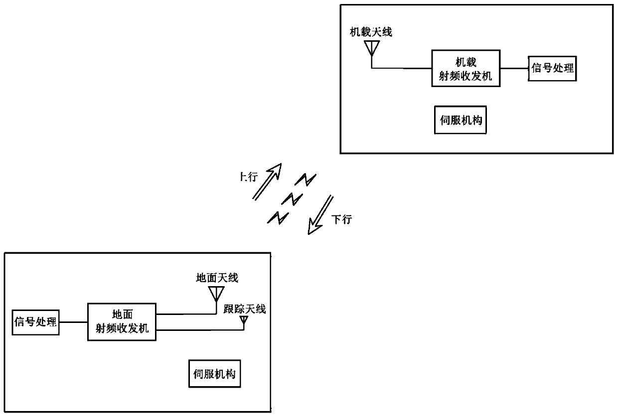
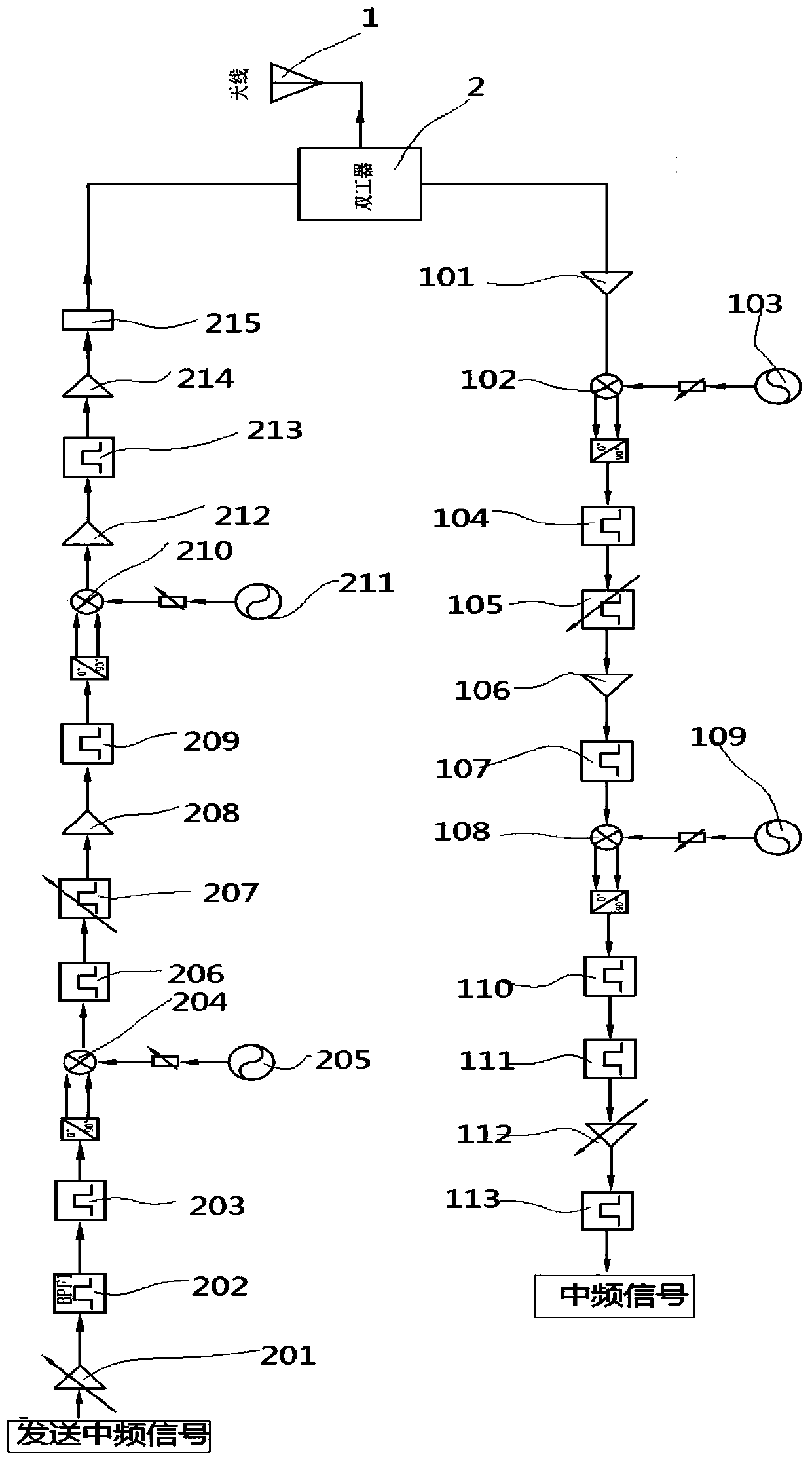
[0028] Embodiment 1, the present embodiment is a Ku-band integrated radio frequency transceiver system, which is suitable for two-way communication between unmanned aerial vehicles and the ground, such as figure 2 As shown, it includes an antenna 1, a radio frequency receiver, a radio frequency transmitter, and a frequency source; the antenna 1 is respectively connected to the radio frequency receiver and the radio frequency transmitter through a duplexer 2 that isolates transmitted and received radio frequency signals.

[0029] In fact, there are two types of antenna 1, one is the airborne antenna on the UAV, and the other is the ground antenna of the ground equipment. The specific indicators are as follows:

[0030] Airborne antenna: frequency: 12~14.5GHz, gain: 20dBi, axial ratio: ≤3dB, port standing wave: ≤1.5.

[0031] Ground antenna: frequency: 12~14.5GHz, gain: 39dBi, axial ratio: ≤3dB, feeder loss: less than 2dB, standing wave: less than 1.5

[0032] The specificatio...


PUM


Abstract

The invention provides a Ku waveband comprehensive radio frequency transceiving system. The Ku waveband comprehensive radio frequency transceiving system comprises an antenna, a radio frequency receiver, a radio frequency transmitter and a frequency source. The antenna is respectively connected with the radio frequency receiver and the radio frequency transmitter through a duplexer for isolating transmitted and received radio frequency signals. The radio frequency transmitter comprises an up-converter, wherein The up-converter comprises a first-stage up-conversion mixer for up-converting an intermediate frequency signal into a modulation signal with the center frequency of 280HMz and the bandwidth of 40MHz to increase the frequency to an L waveband, a second-stage up-conversion mixer for up-converting the modulation signal with the L waveband to increase the frequency to a Ku waveband. The radio frequency receiver comprises a down converter, and the down converter comprises a first-stage down-conversion mixer for down-converting a received Ku-waveband radio frequency signal into an L-waveband modulation signal and a second-stage down-conversion mixer for down-converting the L-waveband modulation signal into a 200MHz intermediate frequency for output. The Ku-band comprehensive radio frequency transceiving system has the advantage of Ku-band communication transmission.

Description

technical field [0001] The invention relates to the field of radio frequency transceiver systems, in particular to a Ku-band integrated radio frequency transceiver system. Background technique [0002] For a long time, radar systems and communication systems have developed independently in their respective fields. With the advancement of science and technology and the upgrading of military electronic systems, new requirements have emerged for both radar and communication systems to have hardware unification and software compatibility. The hardware composition of radar and communication systems is basically the same, and their functions are realized through the process of transmitting and receiving electromagnetic waves; at the signal level, the signals detected by communication and radar have become similar, the operating frequencies overlap, and the signal modulation characteristics There's not much difference either, so sharing the hardware and software of both is theoreti...

Claims


Application Information

Patent Timeline
Patent Type & Authority Applications(China)
IPC IPC(8): H04B1/40H04B1/04H04B1/10H05K7/20
CPCH04B1/40H04B1/04H04B1/0475H04B1/10H05K7/2039H04B2001/0408H04B2001/0491
Inventor 卜景鹏马向华汪雄剑官国阳刘进军
Owner GUANGDONG SHENGDA ELECTRONICS
Learn More